
Rewanui is basically a shunting plank. Operationally, it is simply no fun without effective and reliable means to couple and uncouple vehicles. Additionally, it’s over 1400mm off the ground and surrounded by trees and the odd structure, so any ‘hand of god’ stuff needs to be very occasional at worst. In short, Rewanui’s success as a layout (in this incarnation at least) is entirely dependent on reliably working autocouplings. I’ve published video and hints in various places over the last few months, but in this post I spill the beans on how it was done.
Experienced modellers will know that Kadees might work, but I ruled them out immediately as looking nothing like the prototype. There’s a number of UK systems I quite like the look of (Alex Jacksons etc), but almost all of these need (or greatly benefit from) twin buffers, which the NZR did not have. I’ve played with ideas for many years and slowly settled on using prototype chopper couplers with a magnet in the hook and a far larger magnet under the baseboard to make it move.
So it’s all good. A magnet fitted within the hook means the hook can be flipped up (and down) for endless hours of entertainment. For a completely reliable layout, however, the devil is in the detail. What I describe here works for me and should be broadly applicable. Doubtless it would be possible to tweak things around a bit if this arrangement did not entirely suit somebody else. There is no doubt that magnet sizes could be reduced and/or distances altered. I’ve settled on the numbers quoted as they are very reliable. One might prefer a less obtrusive magnet in the hook (I would, and I have tried it), but smaller here means a larger actuation magnet, shorter distances or lower reliability. The values and dimensions here are pretty bullet proof and work without exact alignment – which is what you want, particularly in an exhibition environment. But other combinations may well better suit other situations. I’m not sure the solution is scalable. HO, possibly, but any smaller would be hard to fit a magnet to hooks (and such small couplers would be difficult anyway). In larger scales, the distances become relatively large with a concomitant need for large magnets that may be inconvenient. A variation would likely work extremely well for OO9.
If one wants the couple/uncouple cycle to work all the time, every time, then the following matters need to be considered:
Accurate, prototypical coupling
I use my own castings which are pretty close to scale. Peter Ross discussed couplers in a Journal many years ago (August 1997) and the issues raised there remain germane. The dimensions of coupler head, hook and pins need to be consistent and complementary so that they readily couple, remain coupled in transit and uncouple when required. Not all couplers offered for sale fulfil these criteria and furthermore not all couplers interact appropriately and consistently with other brands. If complete reliability is the goal then it pays to stick to just one coupler type that works reliably. Castings need to be cleaned up carefully and it is useful to have master couplers to check that each new coupler will work with the rest. I generally use brass black to colour the castings rather than risk paint gumming things up.
To be frank, while these couplers work well in standard form, manual uncoupling is not always that easy. If wagons are brought together and the hook lifted it works perfectly. The problem is that this often requires three hands. Trying to lift the hook without removing the tension in the train can be difficult (as it really should be). But with autocoupling (or with a magnetic wand) it’s all a lot easier.
Generally high standards
Chopper couplers can work really well, but sudden stops, bumps and jolts can cause even the best of them to part. Overall a layout needs to work smoothly and reliably before even thinking about trying this. Good trackwork, good electrics and compensation/springing will all help to minimise shocks. Good slow running is also pretty essential if you want to gently snuggle up to a stationary wagon rake. If you need to poke your trains from time to time to keep them running, then hands free uncoupling possibly isn’t going to add that much to your operational pleasure.
Coupler centring and set up.
It is essential for automatic coupling up that couplers are at the same height and centreline as well as being centred before vehicles are brought together. While there is some tolerance, reliability declines with variability. Coupler height is achieved by using an appropriate jig and packing couplers to suit. Most of my vehicles are sprung, which complicates matters a bit, but the principle should be obvious. Clearly the hook needs to move very freely on it’s pin. If it’s stiff then there is virtually no chance a vehicle will couple up or that the magnets will lift the hook to uncouple.
Intuitively, coupler centring seems important but I suspect it may not be. All couplers in a train that has run are inherently centred and if you only use autocoupling then they always will be as there are no side forces to misalign the heads. Centring is handy for new vehicles added to the track, hand shunted etc. I wouldn’t argue against centring, I’m just not sure it is as practically important as one might expect. I use magnet pairs for centring as well. Good centring action, low force and easy to set up.
A simple jig to ensure magnet orientation is correct. On the left the centring magnet is checked and on the right the orientation of the hook magnet is confirmed.
Magnet fitting
I have a hook casting that has an integral slot for a 2mm long 1mm diameter rare earth magnet. Essentially a press fit, reinforced with CA glue. Very easy to do and consistent every time, but you need to ensure the orientation is correct, for which I use the jig above. Just looking at the hook, the magnet is a bit obtrusive, but once fitted to a coupler and installed in a train it really is not. The magnetic field is aligned with the hook . It really needs to be so it fits, and this may seem a bit counterintuitive. All I can say is that it works well.
My coupler castings have cast in voids for centring magnets, cast in drag pins for the non-hook coupler and press fit drag pins for the hook. So installation of couplers to each vehicle is pretty painless. If hooks without magnets are already installed, it is easy to swap them out for a retrofit.
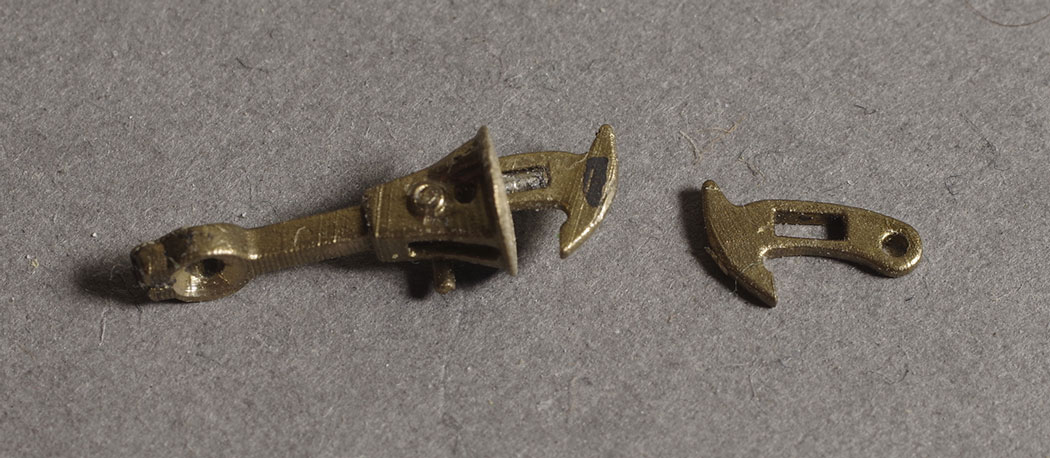 Magnets and hooks. The hook with integral magnet slot is on the right. On the left an assembled coupler with magnet fitted shows that the install is not especially obtrusive. When coupled it is not visible at all, so this is only a very minor consideration at one end of a train or rake.
Uncouplers
My uncouplers are servo mounted. Other mechanisms would undoubtedly work. In my case I’m invisibly bringing an 8mm, 6mm diameter magnet under the hook, beneath the ballast, which provides plenty of lifting force. The magnet to drop the hook is smaller at greater distance as the force required is much less. The fields of the coupling and uncoupling magnets reinforce each other though, generating a little extra lift. The ballast in my yard is well over the sleepers which helps, but a bit of tweaking would allow it to work on exposed sleeper tops too.
Obviously this means uncoupling can only be accomplished where an uncoupler is installed. I haven’t found this to be especially limiting, and Rewanui only needs 7 uncouplers to work prototypically.
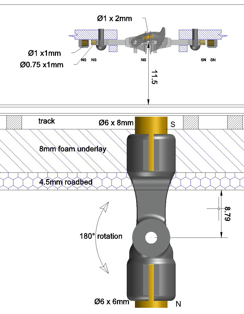
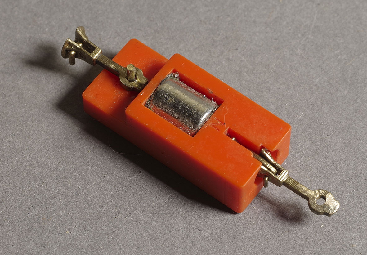
Uncoupler schematic. Dimensions are chosen here to suit my layout construction and to place the uncoupling magnet just below sleeper top. This height would be fine in many yards where the ballast covers the sleepers. All magnets shown in yellow with polarity indicated (NS). The large rotating magnet carrier (shown in the ‘uncouple’ position) is a 3D print arranged with a spline to fit the common 9g servo. The servo mount (not shown) is also 3d printed, which makes the whole installation very straightforward.
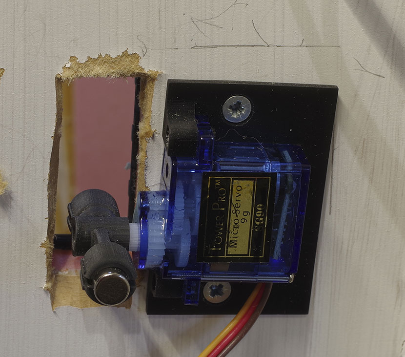
An uncoupler installed under the baseboard and in the ‘couple’ position. At this point the thin cover at sleeper top has yet to be installed. I have another version of the servo mount with slots rather than holes for the mounting screws to allow adjustment.
Lubing
A bit of graphite (soft pencil lead) can work wonders encouraging reluctant hooks to behave and slide freely on coupling.
If it goes wrong
For the very rare occasion things don’t work (and, in our case, fiddle yard operation), it is worth making up a ‘magic wand’ with a magnet on the end. This can be used as a non-contact manual uncoupler. It doesn’t look great compared to autocoupling, but works way better than the alternatives. In fact even if you don’t want autocoupling, a hand held wand and magnetic hooks makes NZR choppers much more pleasant to use.
At this juncture the system has been prototyped and developed on and off for quite a few years. The current implementation is pretty simple to install and set up and is fully installed in the Rewanui layout. It works more or less 100% in both coupling and uncoupling. From time to time, if positioning is average, hooks can fail to lift and occasionally free-running wagons will move instead of coupling up. However a second attempt almost always works without recourse to any manual intervention. This isn’t troublesome or visually intrusive to operation, as something similar happened on the real thing from time to time. Generally any failures can be traced to a particular out of spec coupler or vehicle that needs a tweak. As these are addressed failure rates fall dramatically.
The uncouplers are all on servos connected to the DCC-Ex system and displayed on the mimic diagram of the touch screen control devices. This is very cost-effective to set up and simple and easy to use with a simple radio button to toggle couple/uncouple with colour change to indicate status.
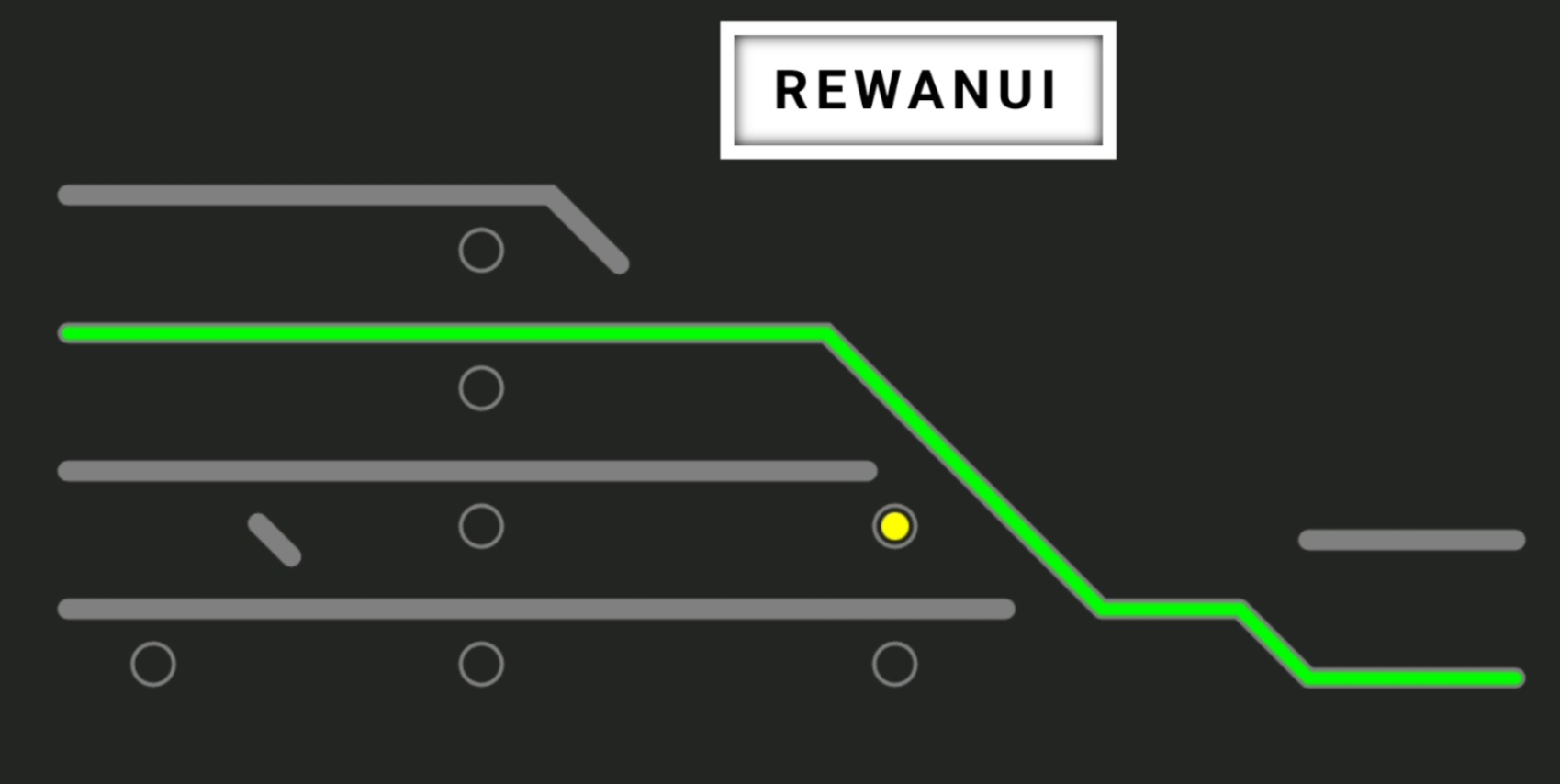 Screen capture of the touch screen mimic for the layout. Uncouplers are the open circles, yellow when in the ‘uncouple’ position.
The main downside at present is that the servo mechanism is relatively noisy. I’ve used very cheap servos to date, and a modest investment may well improve matters. In any case, this is certainly a solvable problem that I’ll get around to, but there are more important things that need doing first. The other problem is that finding the uncouplers and parallax error mean that one really needs to be in a position to see what’s going on. This isn’t that big a deal either as we’ll find a way to mark the positions and stepping down the layout to check things is no trouble.
It may be worth noting that I use code 83 steel rail. I imagine steel rail affects the magnetic fields somewhat. The method worked fine on nickel silver rail in testing and early tests using stock PECO code 100 were OK too. Nevertheless magnet sizes and distances may need to be adjusted for situations that differ from mine.
Craig Utting described autocoupling as the ‘holy grail’ of NZR modelling, and I agree with him. The ability to reliably shunt hands-free greatly increases the scope of operation and enjoyment. Being able to achieve this without intrusive mechanisms is a significant bonus too.