
At some point in any railway modeller’s journey there comes a time when locomotive and layout control needs to be addressed. For me this wasn’t a sudden thing, but more an evolving process over many years. Completed and conceived locomotives have been designed with sound in mind for quite a while. Given that sounds need to be customised to reflect the NZ prototype this has meant that LokSound decoders were more or less the default, and that’s fine. As I’ve played around with test beds and a developing layout, a venerable NCE PowerCab has met my control needs effectively.
As I look towards a fully functioning layout, means to run trains, operate turnouts, uncouplers and various possible lighting and animations became a more active question. There are many ways to do this, so to start with I should define my needs. These are:
- Clearly it will be DCC.
- Rewanui is an exhibition layout, so any solution needs to work well under conditions where distraction, etc is a given.
- It’s desirable for the solution to be simple with regard to wiring, power supplies and so on. Troubleshooting wiring under layouts under pressure and the risk of forgetting any one of multiple essential components is a risk.
- I want to operate turnouts etc from a digital panel (tablet etc)
- Wired throttles are fine. It’s not a large layout. The option to have a wireless throttle is not a bad idea though.
- Any interface should be relatively large format. When interacting with the public, operators should not be peering at a handheld device, and if the public can see the interface that’s all good.
- I only need a small subset of DCC’s power. Rewanui will have 2 locos at most active, there are no signals, half a dozen turnouts, no consisting, simple loco lighting and so on.
- I don’t need to run DC locos.
- I don’t need decoder programming on the layout, or at least not on the operating interface.
- We’ve some plans for running an integrated clock and timetable to reflect the real trains
For the most part, these needs are easily met using just about any commercial DCC system and JMRI’s PanelPro. There are various static decoder solutions to power the various turnout motors available.
But here’s the thing: I don’t very much like what’s available. Not that available offerings are necessarily poor, but they are generally way more featured and flexible than I need. That flexibility comes with complexity, which I certainly don’t need. And it’s not just me. When I visit the layouts of others it is not at all unusual to see them battling with their DCC set up. All of this can get quite expensive too. Not only in buying the necessary, but in my experience discarding chunks of costly equipment along the way as they are found inappropriate for some reason or needs change.
So what I have in mind is an intuitive control panel to operate the layout, and a throttle that does all I need for an NZR steam locomotive and no more. Although we might complicate matters a bit with the timetabling. Being able to dispense with the unneeded complexity, with a system providing only what I need, should make for a smoother, more intuitive, operating experience.
Around about the time I started thinking about the issue, I went to a clinic by Wayne Hatcher, where he discussed Arduino control of layouts. Arduinos are basically small, cheap (a few dollars) computers that are set up to interact with the real world through easy to access inputs and outputs (I/O). This led me to explore the open source DCC-EX. DCC-EX is a fully featured NMRA compliant DCC system, that can play with JMRI and a number of commercial systems too. It’s based on a standard Arduino board with a motor shield (A board that piggy backs on the Arduino and can control motors and similar functions). I purchased a fully configured command station (CS) for $65, but I could have purchased parts and configured it myself for possibly a third of that.
So there I sat. New command station in hand, reading up on DCC-EX and JMRI, working out how to proceed to develop the overall system I had in mind based on the needs above. Not that I ever planned on doing anything clever, the idea was to pass all the tricky bits to my son Haydn who is adept at these things. As we got into it, however, it slowly dawned that we were making it far too hard.
What the DCC-Ex command station (like any other command station) does is pump out data packets that tell connected decoders what to do. Instructions to the DCC EX command station are simple text. For example a command to alter locomotive speed takes the form: “<t cab speed dir>” where cab= Address of the loco; speed= 0-127; dir = 1 (forward) OR 0 (reverse). You can send this text to the CS via an attached keyboard and get the expected response. This is not practically useful, other than for testing, but it does mean that it is very easy to write custom code to control the layout if this is your thing. It very definitely is our thing but, if it isn’t yours, JMRI will handle it and the communications will hum along in the background without you ever having to know anything about them.
The other thing about using Arduino based hardware is that there are a lot of very cheap boards than can be added for various input (sensors) or output. These are not DCC items as such, but they are able to be controlled by the DCC-EX CS. For example a board to control 16 servos is around $4.
So how easy is it? This little anecdote should illustrate. We’d taken delivery of a bunch of bits (The CS, a few servo cards) and other things (like power supplies) were on hand. In typical father-son fashion we both knew we were on the same page, but totally were not. So with a Stanley cup game nearing it’s conclusion in the background, Haydn connected the CS to his laptop and more or less immediately deleted the installed DCC-EX software (the main reason for me paying a premium for the gear in the first place). At this point there was a major fight going on at the hockey. There was a minor fight going on at home over the deleted software too. By the time penalties had been assessed on TV, Haydn had downloaded the software and reinstalled it, which calmed matters at home a bit. Connecting the boards was easy with standard connectors, no solder required. We did butcher a little USB 5V power supply board ($3) by removing the USB socket and wiring to the +5V and Gnd pads to convert the incoming 19V power to 5V for the servos, but that was pretty simple. So at this point the CS was connected to Haydn’s laptop (for set up), and also to a servo board, with servos attached. With text commands on the laptop we could operate any of 16 servos (turnouts), with control of travel and speed. And the hockey game hadn’t finished yet. So, pretty easy.
The next step was to control a train, and for this purpose I mocked up a pre-programmed decoder with head/tail lights and motor. The 19V supply was connected to the CS and the track supply was connected to the ‘locomotive’. The <t cab speed dir> command was duly sent – nada! Fn0 was toggled to get lights – nada! Remembered to plug the power supply into the wall and voila! Lights and action. Again, pretty easy.
This probably sounds a long way from a slick model railway control solution. However:
- Configuring a user interface (ie a touchscreen with buttons) to send text strings is very doable and not especially complicated.
- There are off the shelf means to send commands to DCC-EX that are outside the scope of this post
- We had, in short order, a system that would act on the strings for a real word result. In other words the hardware was sorted.
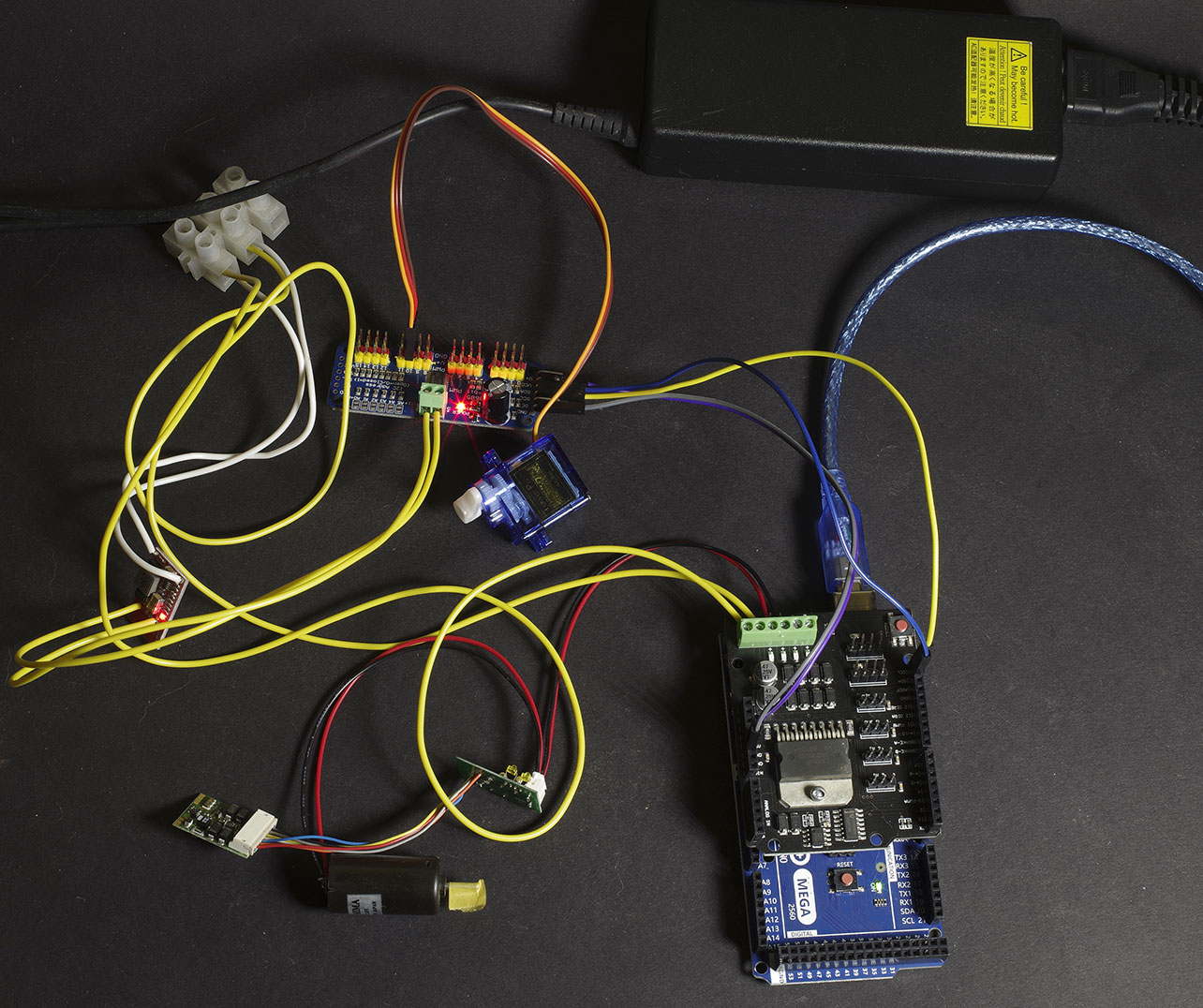
Here’s the test set up. The DCC EX command station is at the lower right. The Arduino Mega is the blue board with the black motor shield clipped on top. It’s comms come from the blue USB connection. At top is an old laptop power supply putting out 19V. This is overkill and getting towards the 20V top end of the CS that I have, so will probably be replaced with something doing 15V. At lower left is my test ‘loco’ consisting of a decoder, motor and F/R headlamps (LEDs on the board). This is wired (black/red) direct to the track output on the CS here. The chocolate block at the upper left is distributing 19V from the power supply to the input of the CS (green terminal block). The white wires connect the 19V power supply to a small 5V regulator rated at 3A. This 5V supply powers the servos via the board in the centre. Power to the board comes from the CS (which cannot supply sufficient current for the servo load on these pins). 1 servo is shown connected. This set up simulates a complete layout operating turnouts (and/or signals etc) and locos. It would be adequate for many, if not most, smaller layouts. More turnouts can easily be added (up to 16 on this board, but boards can be daisy chained to allow practically unlimited servos). Normally locos would be on the track connected to the track output on the CS. The command software (throttle, JMRI PanelPro etc) communicates with the CS via the USB connection.
So at this point we had essentially prototyped a layout with turnouts and locomotives that we could control. The control interface so far remains totally impractical, but it does work. Our next steps are to play with custom interfaces that suit what we want to do. These will probably be running on a Raspberry Pi connected to the CS by USB. But we could just follow the well tested route and install JMRI to provide the interface, and WiFi is an option. There’s a learning curve to that, but it is designed for railway modellers to follow so should be a somewhat simpler route than the course we plan to sail. This is just one way to set up DCC Ex, and there are others that may better suit different situations.
DCC EX is a DIY sort of DCC solution. But it is not at all hard to do, and in fact not much harder than setting up a proprietary box. We purchased a built up unit that came programmed. However ‘assembly’ involves plugging 2 boards together, and we’ve assembled and disassembled ours a few times (I’ve no idea why, young adults just like to fiddle). Firmware set up involves not a lot more than downloading the files and copying them to the Arduino over a USB connection, and can be done in a few minutes. It worked perfectly out of the box (user errors and youthful ineptitude notwithstanding). All for around $100 too.