
I’ve been contemplating the next steam locomotive project, now that the F kits are done.
The Wa is a fairly obvious candidate as it appears to have so much in common with the W. With that thought nestled cosily in a corner of my mind, I optimistically set out to discover what might be needed to take the existing W and produce an accurate Wa. Greymouth had 217, 137 and 289, all equipped for incline running, so there is a good personal incentive as well.
It’s worth perusing pages 70-71 of Lloyd’s Register (2nd ed) as this has photos of all three Greymouth examples in one spread. The first thing that strikes is that just about every detail fitting differs between the three. Domes, air reservoirs, clacks, toolboxes, cowcatchers, whistles and much else besides. Even the little doors hiding the reversing gear are arranged differently. However, these things are relatively trivial as they are rather like baubles on a Christmas tree from a modelling perspective. Essential to the look, but easy to change around. Wa217 had an extended cab too, but this also is not too much trouble to address. Some Was had the little cab vestibule that featured on W238 – but this is already sorted.
Differences from the W are, in fact, relatively few. Key things are:
- Larger wheels – this is easily addressed and in fact the North Yard wheel is closer to the Wa than the W.
- The Wa footplate is not continuous across the top of the cylinders, so a new footplate is needed together with some thought on how to keep everything located during construction as the footplate did that in the W kit.
- The Wa trucks are quite different to the W but it is a straightforward swop.
- There’s a splasher for the front truck, but it’s flat sheetmetal.
- Frames are slightly different, particularly in regard to cutouts and also how to arrange the build, as the 2 piece footplate will make joining the front headstock/footplate a little different. Very similar though, so easily done.
So that is all good. There will be some new detail castings, but much already exists and the new work will follow the W template even though it will look a bit different.
So just the cylinders and motion to sort. A combination of tapping shoulders, visiting Ferrymead and cries for help on Facebook produced a very good selection of drawings that, while not entirely complete, was more than enough to do a very accurate 3/16″ model – I thought. And this is where it started to get difficult…
The 11 members of the class were delivered over 11 or so years at a time when NZR and locomotive design generally was advancing rapidly. The initial 8 locomotives had slide valves while the last 3 had piston valves. You don’t see the valves in the model, but you do notice that the valve chests and cylinders are very different between the two. But I knew that already. Starting to work up drawings for the two, it quickly became obvious that NZR didn’t see fit to distinguish between the two types in the drawing titles. Furthermore the Was were originally classed W, so many of the drawings are named somewhat ambiguously. I was ready for that too though, from experience with the W. And then I noticed that there are actually (at least) THREE styles of motion on these locos.
The piston valve engines have the common style twin slidebar with the cross head between ( Locos 50, 68, 137). The slide valve engines have a completely different style with the crossheads slung under the slidebars. However, on some the crosshead is under a single slidebar (165, 217, 220) and on others it is under a twin slidebar (288, 289). I’ll refer to these as types A, B and C respectively. I cannot see an obvious pattern as to dates or building workshop to explain the difference between type B and C. Of course, these differences then also affect the motion bracket and the various linkages. As with the F project, it’s a bit like doing a jigsaw where some pieces are missing and the pieces you do have are from a number of different puzzles.
Type A is relatively easy to sort out. Ferrymead have drawings of all of the parts including a general arrangement. Likewise I have good drawings of the cylinders, valve chests and their clothing. The valve spindle guide is much simpler on these locos compared to the W, being a straight cylindrical section that is easy to model.
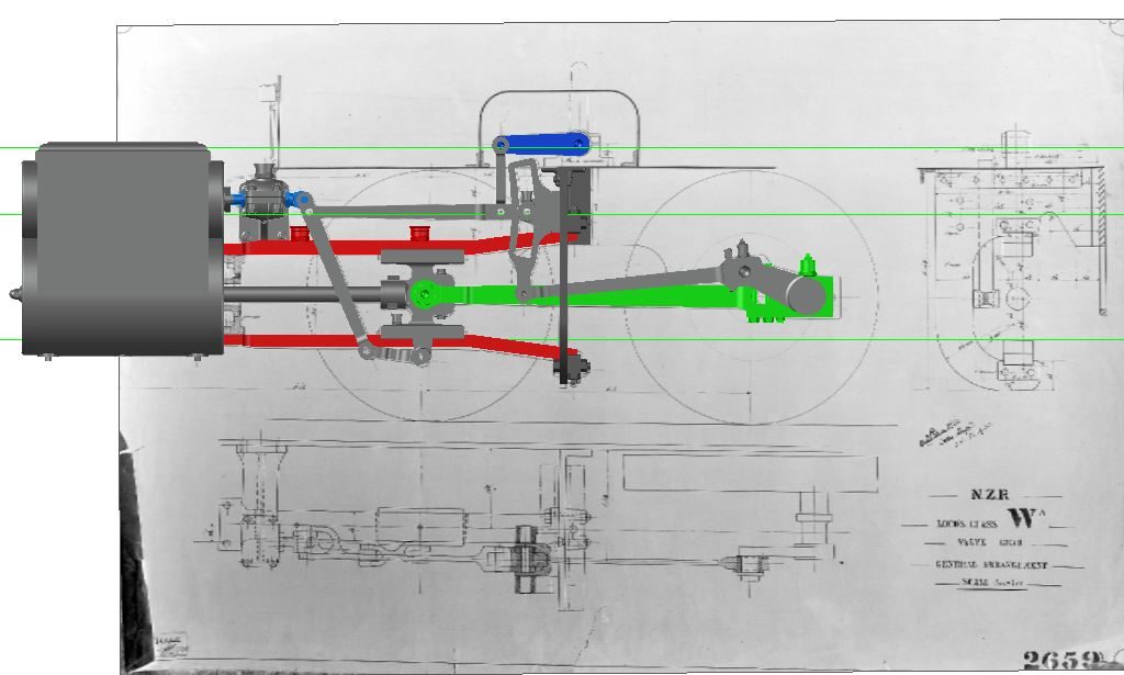
Type A valve gear modelled with the GA in the background.
Type B is also OK. Caleb Scott came up with a GA for the gear. I have good drawings for the cylinders, valve chests and crossheads. The radius rod, lifting links, expansion link and eccentric rod are all as per type A or close to it. The valve spindle guide is also the same as for type A. The main difference is the combination lever which is cranked out at the top and inclines inwards at the bottom. No drawing for this, but there is enough in the GA to work it out. The motion bracket is obviously much smaller without a lower slidebar to support.
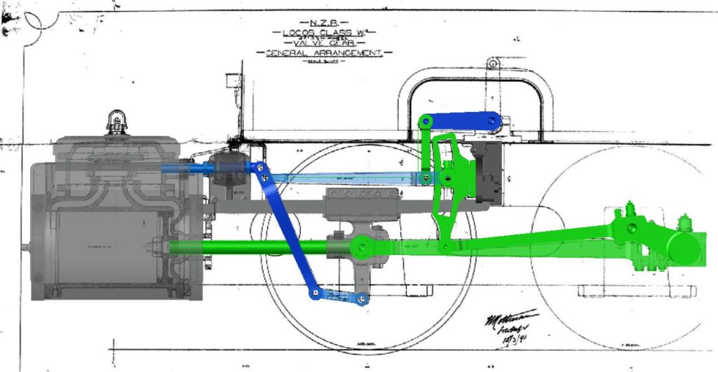
Type B gear
Type C is similar to type B, which is why I initially overlooked it. The cylinders are the same. The crosshead is visually very similar, perhaps identical in the body. However the upper slidebar really gets in the way in similar fashion to the W. This means the valve guide is cranked and the guide is rectangular in section – The guide looks like it is the same as for the W, so that at least is done and proven. The only drawing I have for this motion is the Locomotive GA and the gear details are not very clear. However with the commonality between type B and the W it will be possible to do something that looks the part.
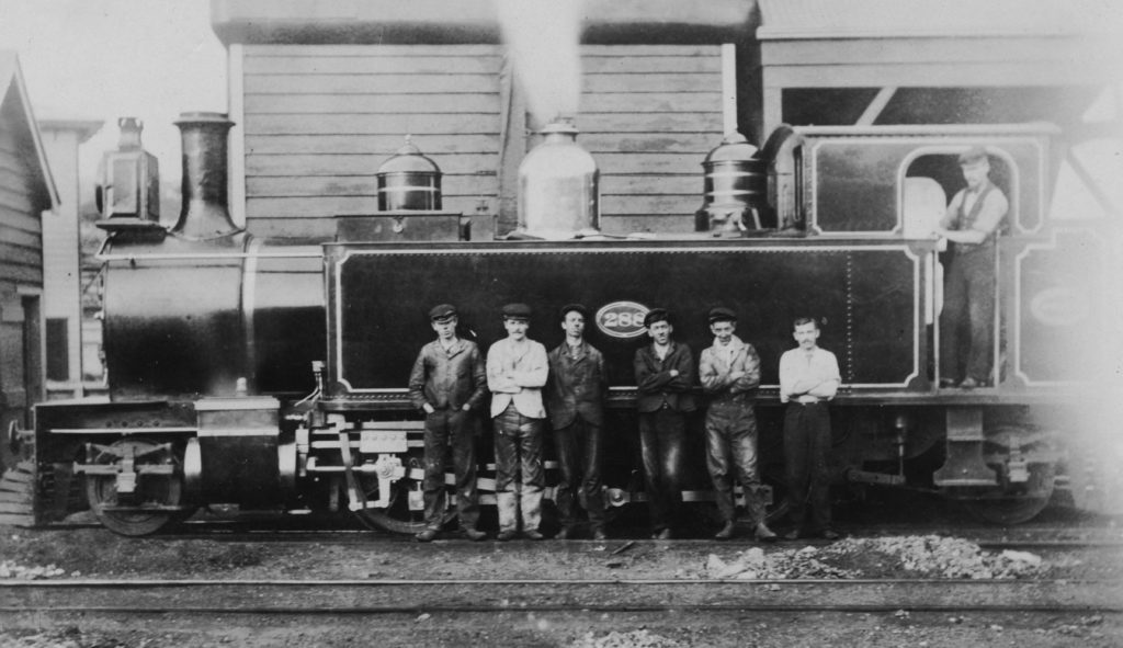
This 1899 photo is probably when brand new. The type C twin slidebars are clear. The only provenance I have for this photo is ‘J Leach Coll’.
So with my jigsaw puzzle completed, I now just need to make the parts. It’s tempting to do just one version, but the Greymouth trio have one of each form of gear, so chances are they’ll all get done.
3 comments