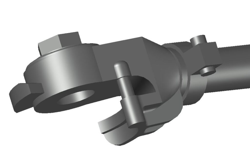
I have often been surprised at how relatively fast building models can be compared to finishing and detailing them. This can be especially true of basic kits where the supplier gives you the relatively easy bits but leaves you up to your own devices for all the minor parts that are actually the more difficult. My latest wagon builds (illustrated in recent blog posts) have caused me to revisit brake hoses, certainly one of those difficult minor parts (but included with the kits). Not that there was anything wrong with my approach, but firstly I realise I have not written it up and, secondly, some Facebook discussion reinforced my understanding that hoses for my period were reinforced externally with wire wrapping. That same discussion also elicited some details of the various gladhand versions and drawings of the parts as well as a 3D model of the pre-1970 gladhand courtesy of Rick Schreuder. Future versions of these parts will be upgraded accordingly. It will be a subtle upgrade but every little helps.
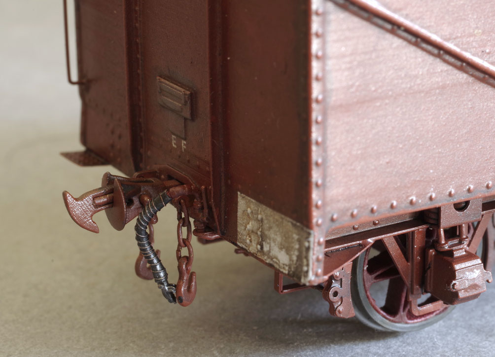
Over the years I’ve used a number of castings from others and of my own to represent the cocks, hoses, glad hands and fittings found at the ends of all vehicles fitted with the Westinhouse air brake. I decided that I did not really like an entirely cast assembly as they are rigid and seem to get in the way. My preferred solution is now very finely cast valve assemblies with separate gladhands connected by a piece of plastic ‘hose’. This post describes how all this is put together.
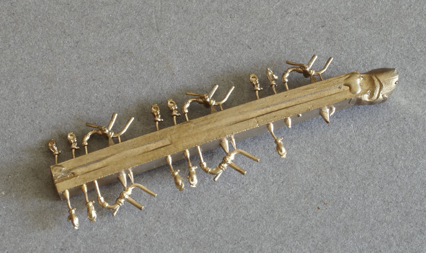
Cast fittings. I do a number of versions of these, but they are essentially similar. They are very close to true scale.
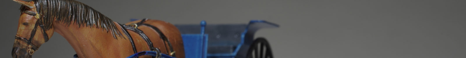
The latest iteration of my castings incorporates a spigot to securely mount the valve and a short length of brakepipe leading under the headstock. This avoids any need to be soldering joints in a confined and visible area. Castings need to be cleaned up and fitted to the vehicle more or less as per the prototype. I generally use a metal blackening compound on the glad hands.
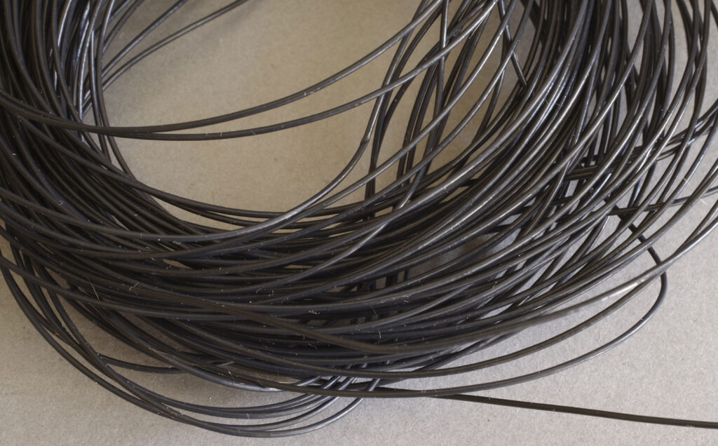
Sufficient brake hose for a lifetime of modelling!
The ‘hose’ is a 0.8mm outside diameter, 0.5mm inside diameter plastic tube. This is soft and flexible with a smooth surface. To represent early linen bagged hoses (pre about 1930) or later internally reinforced hose (diesel era) this can be used as is. It probably doesn’t replicate the softer look of the linen bags perfectly, but it may be possible to distress it a little to achieve that. It certainly needs a little extra work to be made to look like the externally reinforced hose of the later steam era (post 1930).
Early standard hoses were 24″ long, later reduced to 22″ or 9.5/8.7mm in scale. For the period 1930-1970 a wire wrapped hose 22″ long with the original style gladhand (not the FP4 style shown here) is correct.
Some years ago I disassembled some relays, to access their coils as a source of fine wire. Doubtless this can be obtained from other sources, but the copper wire I have is 0.06mm which is a little over scale 1/8″ – not too overscale for hose wrapping in fact. Almost exactly scale #8 wire too, so useful for fencing.
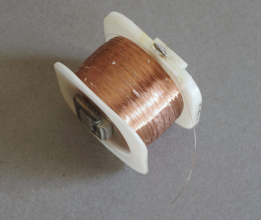
Scrapped relay coils are an excellent source of fine wire: 0.06mm in this example.
Operations like this (ie spiral winding 0.06mm copper around a short length of 0.8mm flexible plastic tube) require a method. It’s just not something you sit down and do as a rule. My trick is outlined hereafter.
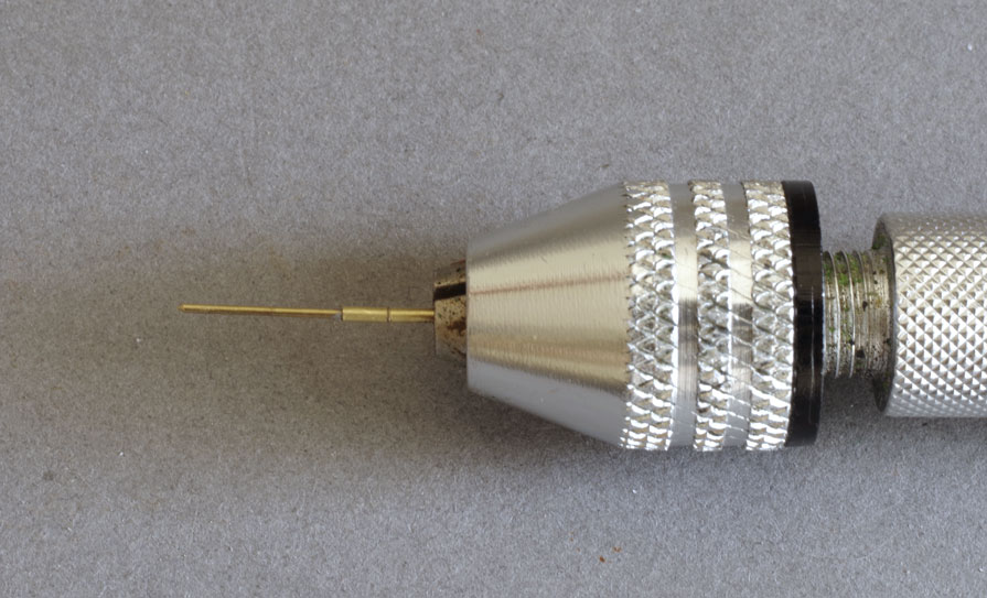
The wirewound hose jig. Basically a piece of 0.5mm diameter hard brass wire ground to a point. A length of 0.8mm tube is soldered over the wire so that 8.7mm of wire protrudes. The whole thing is sized overall so that the jig can be conveniently held in a pin chuck.
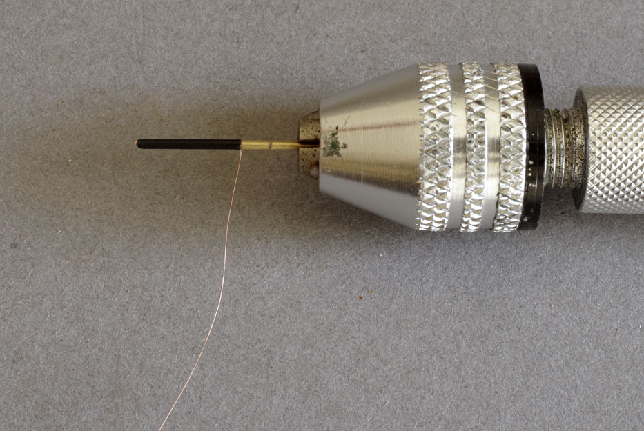
A length of wrapping wire is slipped into a length of plastic tube trimmed to 8.7mm and the tube pushed onto the wire as shown. This is a convenient way to retain the wrapping wire.
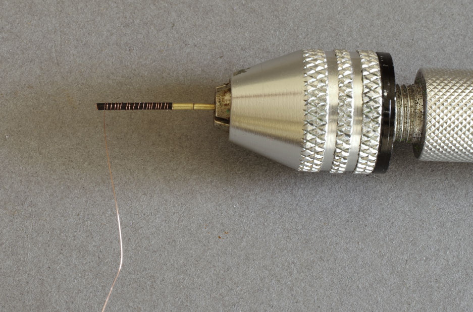
With gentle tension on the wrapping wire, the chuck is rotated to form the wrap. I then trim the excess and apply a little low viscosity CA glue to fix the wrap in place.
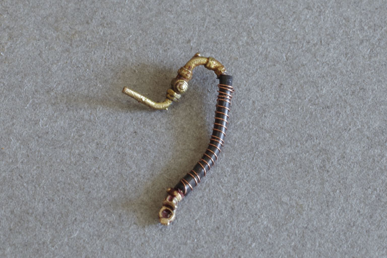
The finished hose can be slid off the jig and fitted to the spigots on the valve and gladhand.
This whole process is a bit arduous for a one off, but if hoses are made in batches it is very quick to make a couple of dozen hoses.
There are a couple of additional steps that can be worthwhile:
- Placing a length of soft copper wire (10A fuse wire) inside the hose holds the hose in position once shaped to taste.
- Crimping the spigots to form a barb improves retention.
- Soldering fine wires (cut to about 7mm) to the gladhand and valve spigots and fitting with adhesive inside the hose forms a very robust hose that is still flexible. Not always necessary, but for something like exhibition use it might be a useful (if fiddly) refinement.
The finished hose.
2 comments