NZR trackwork is always a challenge. RTR track is easy, but inevitably wrong, being intended for other scales/gauges. Injection moulded or printed sleeper bases are much better but still not entirely convincing. Handlaid track is nice but, even with etched bedplates, track fixings are tricky. If you want a Fell centre rail, then it is all harder still. This post describes the approach I’m using for Fell track for my personal modelling.
I only need about 1.5 m of track with centre rail so I can contemplate something laborious, but it is on a curve so accuracy is an issue to be considered. And it crosses a short bridge.
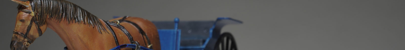
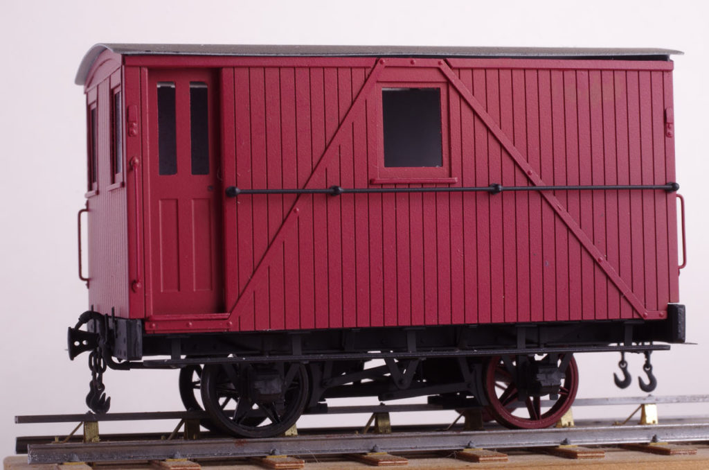
My first try at this dates back at least 15 years and used etched parts. I only built 100mm or so and the Fell van below is posed on this test piece. Grandt Line bolt heads were used for the fixings.
Wind the clock forward to the age of 3D printers and laser cutters…
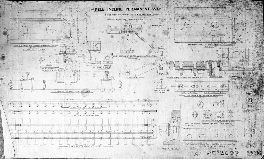
This drawing shows how the centre rail goes together. As the track is subjected to heavy braking, there is a lot of attention to preventing creep down the hill.
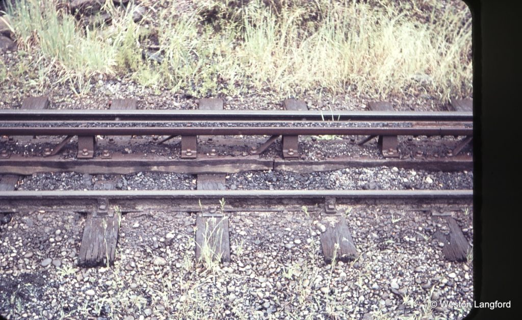
This Weston Langford photo shows the track later in life. Pretty similar, but the centre rail is now offset half a pitch and eveything looks to be retained by screws rather than through bolts. From what I can see from 1940ish images the track at that time was closer to the drawing, so I chose to go with that. The concept this time around was to used 3D printed parts inset into laser cut sleepers. I used 3/32″ basswood for the sleepers and 1/16″ for the central baulks. Not quite right, but the scale 6″ sleeper thickness will be hidden by the ballast and the scale 4″ baulk will provide a little more clearance to the rolling stock,
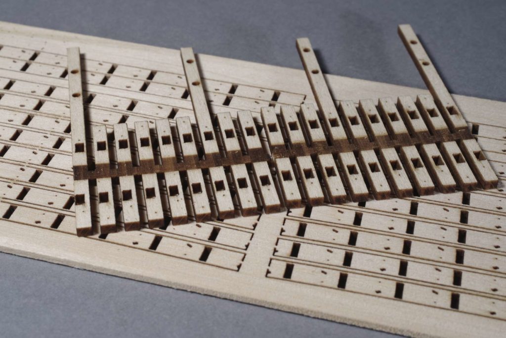
Here is some of the laser cut timber. On top are some sleepers (these are for the short bridge). Note the engraved recess for the central baulk, rectangular cutouts for the bedplates and holes for the bolts fixing the timbers to the bridge stringers. Also some larger holes for the bridge handrails to mount onto. The lower sheet has the timber baulks. These are unprototypically curved to suit my trackplan. The bridge timbers are straight, but the track is curved, which is why the bedplate locations are not parallel to the sleepers.
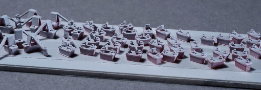
The ‘ironwork’ was printed with substantial feet. These make printing and handling convenient. They were stuck to some double sided tape for priming (as shown) and painting. These parts are very close to scale, although thickened in some areas for practicality.
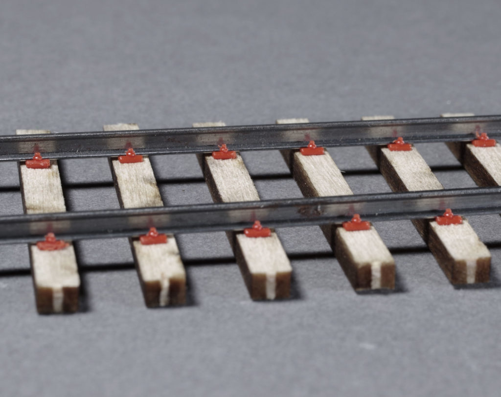
I did some plain track too and assembled this as a first test. There is no glue here, it all just clips together. Emboldened by this I painted and stained up the parts for the Fell track. The sleepers were treated with india ink in iso-propanol, the 3D printed parts were airbrush primed/painted with Vallejo acrylics.
The Fell track prior to fitting the centre rail. As before, at this stage there is no glue used, it just clips together. Despite the chunky 3D parts, the appearance here is nice and fine as the heavy foot is buried in the timber. The feet are tapered so insertion is easy, but the stucture firms up when they are pushed home. The ballast cement will eventually lock them in.
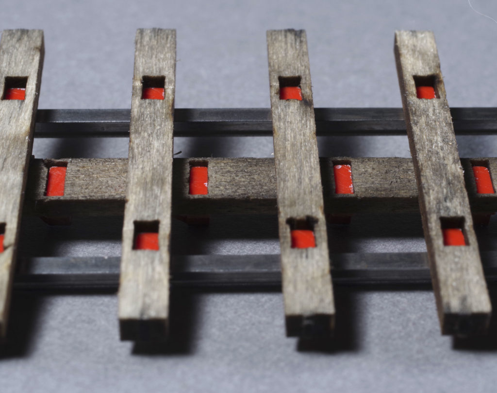
From below the way it is constructed is more obvious.
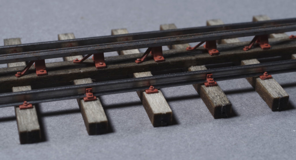
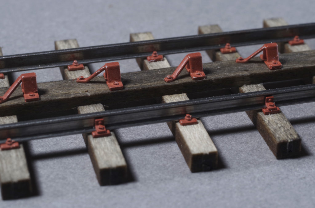
The test piece nearly complete. There’s another fixing bolt to go in the empty holes in the baulk and the centre rail needs bolt heads added. I’m very happy with it though and cost and effort required are quite viable for what I need to do.