
Modelling steam engine underframes
I am the first to admit I have not completed all that many locos, but I have designed a few and completed a lot more running underframes, so maybe that qualifies me for the forthcoming pontification. I’m currently in the throes of finishing a couple, and developing a couple more, so underframe design and realisation are currently top of mind. Steam locomotives of course. This is more of a design philosophy discussion than a ‘how to’, but readers are welcome to contact me for practical details. Future posts may cover the practical aspects.
Any engineering project (and a model loco underframe certainly qualifies) requires some form of specification to guide development and assess the result. In our modelling this is often assumed rather than overt, but I think it’s helpful to list what we want. Underframe requirements are somewhat complementary to track standards and layout design, so not everyone will have the same list or assign the same priorities, but hopefully most modellers would find common ground with:
- Track holding
- Smooth running at all reasonable speeds
- Durability
- Low and simple maintenance
- Prototype fidelity
You can be sure that poor design and/or construction will lead to disappointment in some or all of the above criteria.
In this post I’ll touch on thoughts somewhat specific to modelling the NZR in 1:64, but also of general utility. Most 1:64 NZR steam engines will be constructed from kits which may be a bit constraining, but the principles still hold. In my view it is a bit pointless to live with a design deficiency if this will result in the finished model failing to meet your needs. But specification is a personal thing and provided your specification, if met, will produce a personally satisfactory locomotive then your hobby will be working for you.
Track holding.
If the track on which the locomotive will run is flat, level, gently curved and otherwise exemplary and the stock it will pull is free running then the forces conspiring to derail a locomotive are minimal and the effort required to keep the beast on the rails will be small. Meanwhile, back in the real world, things are not always like that…
It is probably self-evident that a chassis that has all of the wheel treads in (or capable of being in – see below) a single plane and all wheels mounted true to axles that themselves are perpendicular to the frames is more likely to stay on the track than one where these basic fundamentals are not met. Furthermore, if the mechanism is smooth there will be far less chance of a lurch coinciding with a track irregularity and putting the wheels into the ballast. So, if nothing else, care and rigorous quality control of the basics can improve things quite a bit. It is best not to assume that commercial products are necessarily adequate. Often they are not and will need rework or replacement. I don’t mean to run down suppliers in saying this, but rather to point out that running a check to ensure products used fully meet your needs can save much pain and trouble further down the line.
Probably the easiest thing to improve adhesion and track holding is to add weight. This needs to be balanced over the centre of the driven wheelbase to avoid any tendency to lift one end of the loco. If your drawbar loads are heavy or your track is inclined then weight will improve pulling power provided your drivetrain is up to the load and your bearings are good.
With regard to drivers at least, some form of compensation and/or springing can make a huge difference to track holding by keeping all wheels on the track and weighted at all times. As this substantially improves electrical pick up as well it’s a concept worthy of serious consideration. Anyone wishing a full and very comprehensive exposition of all this should consult Scalefour Digest 41 by Russ Elliot.
Compensation/equalisation is a means of using beams and pivots to balance the loads on each wheel. The real thing uses it in conjunction with springing to provide suspension to the locomotive. In models it is usual to use either compensation OR springing and thus the compensation designs are somewhat different and laid out according to the principles expounded in Mike Sharman’s seminal ‘Flexichas: a way to build fully compensated model locomotive chassis’ published back in 1982. The general idea is that by using beams and pivots the locomotive sits on 3 points. As 3 points define a plane, the criteria of having all wheels on the track at all times is met. More than this, however, all wheels remain on the track when the track is uneven providing substantially improved track holding, adhesion and pickup over a rigid chassis. A further advantage is that, with the right design, track irregularities are dampened and not transmitted fully to the locomotive resulting in an improved ride and appearance.
My favoured 6 coupled 3 point compensation solution. The 3 points on which the loco sits are shown in blue (figure after Elliot).
All my locomotives (with the exception of the 0-4-0 Dubs ‘A’) have had 6 coupled wheels and used the same basic compensation arrangement. I have never bothered to extend the compensation scheme to bogies and trucks (although my bogies are themselves compensated). One could certainly do so, butI feel the advantages on a 6 or 8 coupled locomotive with reasonable wheelbase are modest.
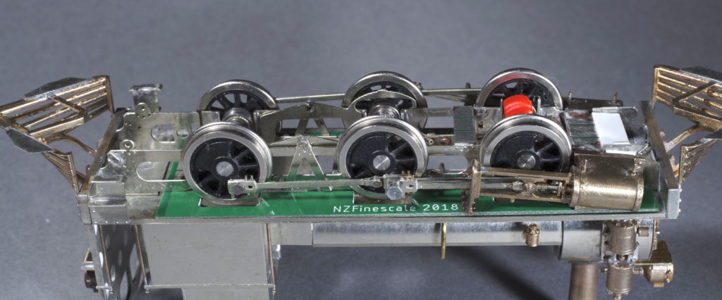
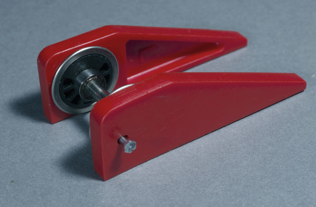
3 point compensation in the F. The orange part on the front axle captures the wheel bearings and is able to rock on a pivot on the loco centreline. The other 2 points are the pivots for the compensation beams between the centre and rear drivers. These cosmetically resemble the compensation of the prototype.
In principle, springing would be a nice way to go, although I have yet to try it on drivers. My view is that acceptable springing would see the locomotive weight carried on the springs so that each wheel carried appropriate weight. The idea of having bearings that are generally bottomed out with weak coil springs (or just gravity) to push wheels into any hollows in the trackwork (an approach used in some NZR kits) is a partial solution that doesn’t meet the need in my view. Similarly, fitting stiff springs that do not detectably deflect under the mass of the loco seems a wasted effort. The issue with springing is that it is relatively complex to set up. Being dependent on the locomotive weight distribution, it can be tricky to design as this is generally unknown at design stage. Elliot provides plenty of information for those interested.
Trucks and bogies can be recidivist offenders when it comes to derailment. It is often hard to determine exactly why, but the following are things I have encountered.
- Wheel friction. If wheelsets do not run freely they tend not to run true to the track and derailment is likely when that happens.
- Insufficient swing. If the track curvature is too tight for the design and the bogie hangs up on it’s pivot, or anything else, then derailment will occur.
- Bogie mounting height. If the bogie mount is above the bogie axle centre then any side force tends to cause wheels to lift. If the mount is below the centreline then side force tends to keep the wheels on the track.
- Light weight. Light bogies can bump off the rails when meeting an obstruction. Added weight or springing is advisable.
- Side control. In the real thing, a truck guides the chassis into a curve. In a model, without any meaningful attachment of truck to body, a light truck can bounce off track as the inertia of a heavy body tends to keep the chassis going straight ahead. A side control spring should help and is generally easy to fit. Pivot points behind a truck will always be a bit of an issue as the truck is constantly inclined to flip 180 degrees. Side control should overcome this.
Smooth running
Getting a mechanism to run smoothly is always a challenge – for me anyway. Approached with trepidation, the exercise seldom fails to turn up some new, unappreciated, wrinkle. There’s also the added concern that a mechanism that’s our best effort will suffer from repeated disassembly and fettling in the quest for silkiness. So having something that will handle repeated disassembly is important, but otherwise many of these fears loom larger for me than they really should and the exercise is rarely as arduous as I dread.
Gearing: Many NZR locos are running around with proprietary gearboxes in ratios around 35:1 from a couple of suppliers. The first thing to understand with these boxes is they have moulded gears that may not be true. That can also be true of the housings. If using such boxes, make sure that the gearset is smooth and lacking tight spots. I suspect much time has been lost chasing down motion binds that are actually in these boxes. After all a bind once per driver revolution could be anywhere in the motion, but this symptom could equally be the gears in a design where all gears have equal numbers of teeth. These boxes are not inherently bad, but some examples are imperfect.
Modern motors are quite high revving as a rule and prototype NZR loco speeds were typically not that fast, so it is possible to use a lower ratio gearset with some benefit. I typically use 50:1, but even lower might be appropriate. A lower ratio will give better slow running and allow a smaller motor to be used.
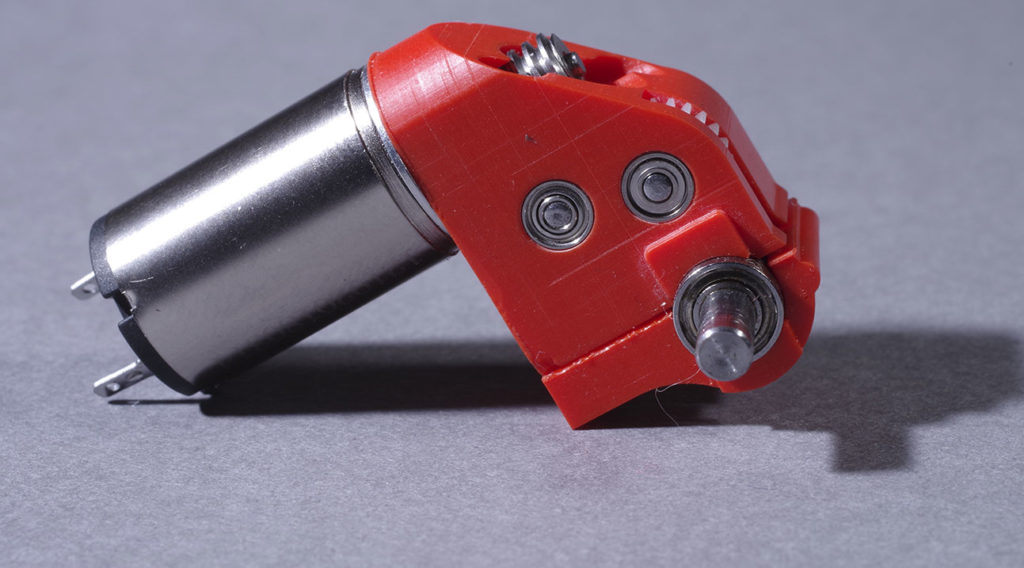
2 stage 50:1 gearbox as supplied with my F loco kit, with a small coreless motor.
Bearings: The availability of inexpensive small bearings from China has opened up options for free running. I like to use ball races for just about everything, but no matter your choice things need to be free. Using ball races for current collection (ie with metal wheels and split frame chassis) may not be a great idea. Certainly as the only means of current collection experience suggests that it is a little unreliable. Using a flywheel, DCC stay alive, or pickups are ways to alleviate any issues.
Chassis set up: There are a few dimensions that are absolutely critical for smooth running. The first is that the rod centres match the wheelbase exactly. In an all etched kit from digital artwork this can be pretty reliably assumed. Otherwise perhaps not. There are various jig drilling, bushing and separate hornblock solutions around that can enable correct set up of the chassis to make sure this criterion is met. Peter Ross summarised a good general method in his ‘Wf revisited’ series for NZMRJ over 20 years ago. Depending on your kit this may be straightforward or a bit more work, but readily achievable in any case.
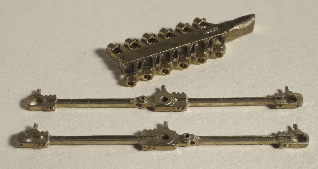
Ab rods. The leading and trailing brasses are separate castings that sit in elongated holes in the rod ends. Soldered in place in a jig they allow the detail level of a casting with appropriate accuracy for good running.
The second criterion is that the crankpin centres are at constant (hopefully correct) distance from the axle centres and that the crankpins are round and perpendicular to the wheel face. This is certainly a possible source of error when screwing crankpins into plastic centres, especially if the centres are from different tools (eg where the counterweights differ between wheelsets). You only need to look at some of the crankpins with the naked eye to see that all is not straight and concentric. Personally, I dislike the plastic centre/screw in crankpin idea as inherently flawed. As noted it’s accuracy is questionable, but most of all it is not very robust and I imagine most builders have ruined more than one wheel due to ruined threads from repeated fitting to tune a chassis. Hex heads look unrealistic too. I’ve used a screw from the back face and a turned bush to form the crankpin, but it is a bit of work and you need a lathe (unless one of the similar commercial offerings such as Alan Gibson, Ultrascale etc can be made to work for you).
The third essential is accurate quartering. Frankly, I always struggled with this until I produced some simple 3D printed jigs that result in spot on quartering guaranteed every time. Unfortunately each jig set only works for one tyre size, but they are easy to draw and fast to print so I have not bothered to come up with a universal solution. But a good jig makes this step painless and is worth finding.
The simple printed quartering jig.
If you have got all the foregoing right then your rods can be a good fit on the crankpins without a huge amount of clearance. That’s a good thing for exemplary running and rods that appear heavy and do not jump around during wheel rotation.
Wherever possible it is a very good idea to get the chassis sans motion working to satisfaction, before adding in the complication of the wiggly bits.
Motion. In my experience a scale motion works really smoothly. The ability to produce such a motion commercially is a relatively recent thing, so many kit builders will have to deal with various compromises. That is not necessarily problematic, but care needs to be taken that the various components can rotate in a plane without needing to twist. Excessive play in valve gear is probably asking for trouble and it looks pretty awful too. Motion components are heavy bits of steel. While they swing and rotate quite quickly, they certainly do not bounce around. I like to keep tolerances tight so that the motion in motion gives the impression of mass.
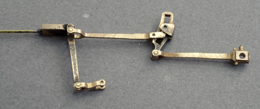
W motion assembly. In this early example I was still using brass pins, but steel is better.
One key to a an effective motion assembly is good technique to make the various pinned joints. The best and largely failsafe method is:
- Drill out both rods true and square and fettle so that the joint has no slop. Test and prove with an appropriate pin. I typically use 0.5mm music wire pins.
- Countersink the back of the clevis (fork) a bit to allow an area for a strong solder join to the pin.
- Treat the end of the rod that will fit within the clevis with metal black (gun blue or brass black). This prevents solder from taking to it.
- Fit an overlong pin to the joint and check again that it is free but not loose.
- Apply a little solder paint to the countersunk region at the back of the clevis and make the joint with a wet iron without lingering.
- Generally you’ll have a perfect joint. Very occasionally it will freeze, but cautious and gentle pressure should release it. I have never had one freeze irretrievably, but leaving the pin well over length will allow easy removal if the worst happens.
- Use a cutting disc to trim back the pin.
Joins made this way allow smooth rotary motion without slop and play. This makes for a visually appealing motion that works very well.
Slidebars, crossheads and piston rods. I like to make my piston rods from steel or stainless. Drill shanks or dowels (from the Emporium) work well or music wire if you have the right size. Whatever you choose make sure that the piston rod lines up accurately with the gland in the cylinder cover. The crosshead/slidebars and rod need to be true so that the rod slides smoothly into the gland over the full range of crosshead movement without slop. I typically solder the piston rod to the crosshead with the rod in the gland and the crosshead between the slidebars. This self jigs everything, provided the castings are reasonably good. I’m perfectly content if everything is really tight at this point as I like to use diamond lapping paste to grind things to a really nice fit. Do make sure that the crosshead has the necessary travel and does not foul either the cylinder ends or motion bracket.
When working the motion by hand it should be joyously smooth. If any components are jumping around then something is tight or misaligned and needs attention. If a sensuously smooth motion is wedded to an accurately coupled wheelset the result should be entirely satisfactory. But if it doesn’t? One trick I use a lot is to work the chassis until a tight spot is encountered. I then gently touch each component with a probe until I find the one that is locked. That is where the problem is. There are a host of potential causes, but once the problem is identified the solution is typically self-evident.
If achieving mechanical smoothness causes you to lose your hair then electrical reliability will surely have you tearing out any remaining tufts. My preferred solution is a split frame chassis with a central, neutral, land in the spacers (suitable material can be had in the Emporium). With metal wheels this removes the need for pickups. With plastic centred drivers, fitting MMW etched phosphor bronze pickups to the frames is easy and effective. The neutral central land simplifies body fixing and so on.
In my view, not much beats a compensated, split frame chassis with metal wheels. All drivers are always in contact with the track and there is a reliable current pathway from tyre to Decoder/motor at all times. Simple, reliable and zero maintenance. A really good sprung solution might be better, but a bit more work to achieve.
I like coreless motors for their high power to size ratio and the generally high standard of engineering. They don’t cog, so are nice at very slow speed. They work best on smooth DC, so it pays to check your controller is compatible. Some back emf controllers are not. Modern DCC is entirely compatible, although the chip may need to be tuned to drive the motor optimally. This is just CV setting according to the manual for the decoder. LokSound out of the box can be very bad before tuning in my experience, but very nice when set up optimally.
Durability and maintenance.
My direct experience doesn’t really qualify me to comment on durability as I have never run my locos all that much. I have observed and talked to others that have. So thoughts are:
Broadly speaking, in a metal kitset engine handled with respect, there is not too much to go wrong. Problems I have seen include:
- Pickups. An ongoing issue and few locos I have looked at are anywhere near 100% in this department. Split frames completely solve it. A Stay-alive on the decoder removes almost all the associated problems, although some of the pickups still need to work some of the time. If you have pickups they will likely need regular maintenance.
- Cracked gears. Moulded gears sometimes crack. Annoying, because the whole quartering exercise needs to be redone and it may not be easy to disassemble everything. I suspect the cracking is due to incorrect tolerance in the push fit bore. An answer may be to ream the bore to the right tolerance and use an appropriate retaining compound.
- Loose tyres, stripped crankpins, out of quarter. Basically plastic centre problems. Plastic centres are not inherently bad, but some examples certainly are. Frustrating. Disassembly, reassembly in appropriate jigs and use of retaining compounds for tyres and alternate crankpin systems as discussed above.
- Worn axles/bearings and worn gearbox bushes. Stainless steel axles in brass or bronze bearings actually wear relatively quickly, as do worm shafts in bronze bushes. Not a problem for an occasional runner, but certainly for a loco that might run significant miles at an exhibition. Ball races should be more durable. Regular cleaning and appropriate lubrication ought to help.
- Chassis design that allows easy removal of the drivetrain is a good idea as, should issues arise, it is at least relatively simple to repair or replace.
- Lubrication. This needs to be appropriate. No lube at all or grease that has dried out will be problematic. Clock oil (or one of the light oils intended for models) is probably best for most purposes, but graphite and lithium grease have their uses.
Prototype fidelity.
A glance at old magazines will show that model steam loco underframes used to be pretty dire in regard to fidelity. Appropriately, more emphasis was placed on practical matters. Some available kits have their genesis in those far off days and accordingly reflect those earlier standards. These days it is possible to have an underframe that looks great and works well.
It should not be too surprising that if underframes are constructed on sound principles without unnecessary compromise, then good looks are not hard to achieve. Wheels and motion that are well set up will also look realistic. Split frames allow the use of metal brakes and sand pipes at more or less scale distances.
My personal preference is to use more or less scale wheels which are substantially narrower than RP25-110 typically used. As a result, cylinder centres can be more or less scale which looks as it ought. Using RP25-110 wheels inevitably means bringing the slidebars outboard quite a bit. That has flow on effects for the rest of the motion if it is outside. It’s achievable and can look good, but some care is needed to arrange and integrate the out of scale/out of line components. This paragraph might be better placed at the top of this missive as, should it be a problem, there is a strong possibility it will be difficult to fix. I tend to draw and 3d model the motion, before making any parts, to identify problems early. With scale wheels on slightly undergauge (16.5mm) track things are not too bad as the motion can be built more or less to scale and still have workable clearances. For kits, the designers have hopefully produced parts that work but, if replacement or reworked parts are going to be used, this is an issue that needs consideration.
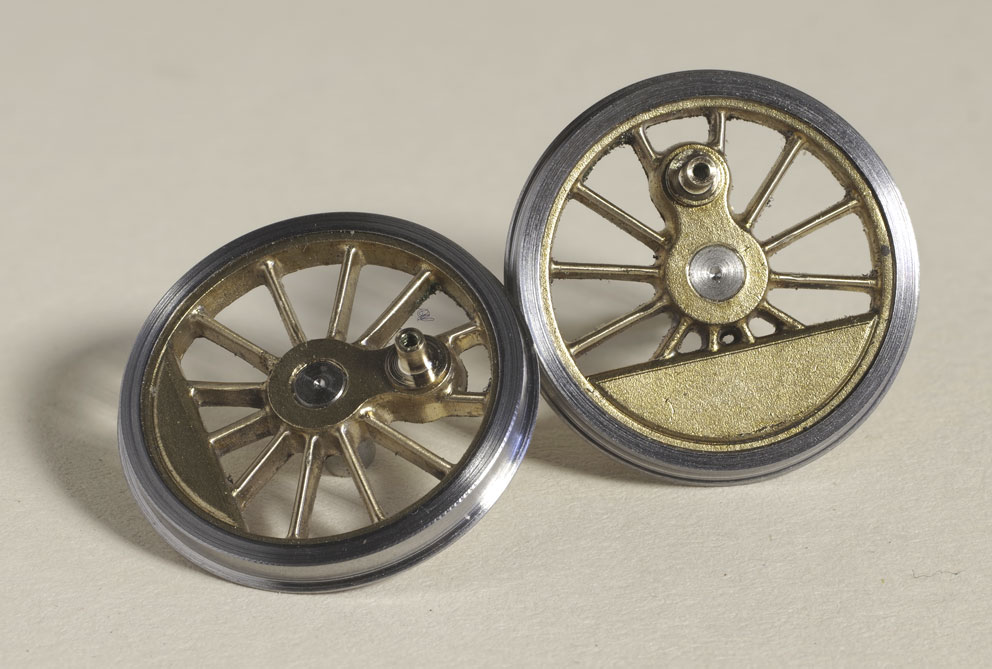
Wheels for my occasionally developing Ab. Very accurate digital patterns – crankpins turned on the wheel – steel tires turned on the stub axle.