Track has always been a bit of a problem for the NZR modeller. Does one use something proprietary, with it’s virtues of speed, simplicity and robustness? Tempting as these virtues are, commercial track bears little resemblance to NZR practice. Worth considering for a yard with buried sleepers, but not good where the structure is visible. For plain spiked rail, wooden sleepers and spikes are viable. However, not all plain track is spiked. Copperclad construction is robust, but lacking in detail. It is certainly possible to use individual bedplates, but mind-numbing to attempt. More complicated track can be modelled successfully with 3D prints as in my post on Fell rail.
The time came at Rewanui to consider the track structures (turnouts) for the yard. For the most part the turnouts are buried, but the Y at the entrance is pretty exposed as are the switches on all of the turnouts. Many years ago I built the turnouts from copperclad PCB sleepers with rail soldered to them. Looking back, the results do not really satisfy although they would work well enough.
In re-evaluating the turnouts I developed a mental specification for the perfect solution:
- Based on prototype practice. I have drawings for the 1926 70lb turnouts as a basis.
- Adequately detailed. Primarily I was interested in the switch area, but there are other things that show even in buried turnouts.
- Hopefully simple. I’ve never eschewed difficult bits, but I’m self-aware enough to realise that easier tasks are more likely to get done quickly.
- Robust. Exhibition layouts take some knocks and turnouts need to withstand the stress of mechanical operation, so rail fixing needs to be firm.
- Ideally a means to avoid polishing the guard rails and frog wings when cleaning track. These should remain rusty as the wheels do not run on them.
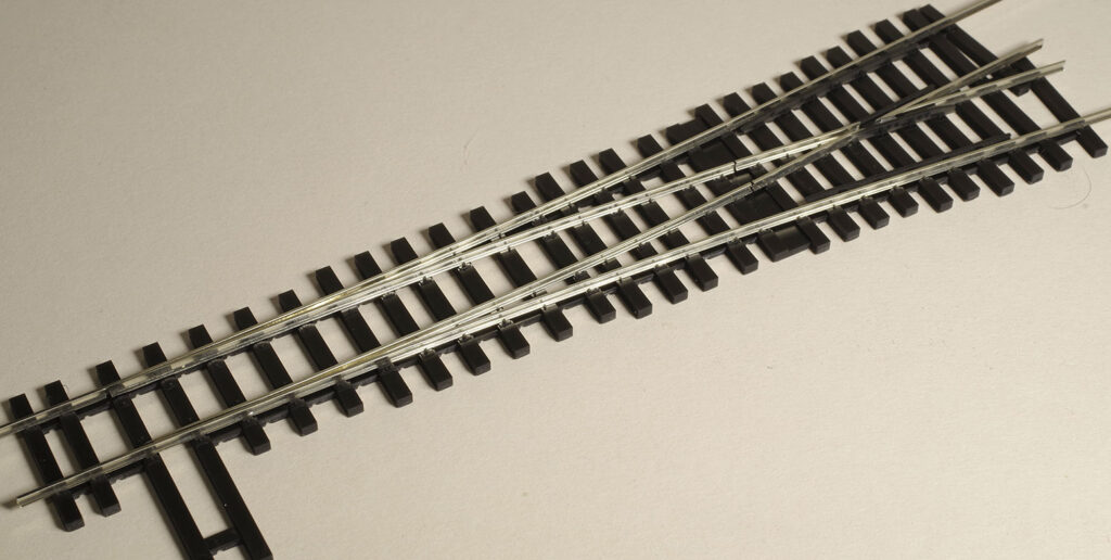
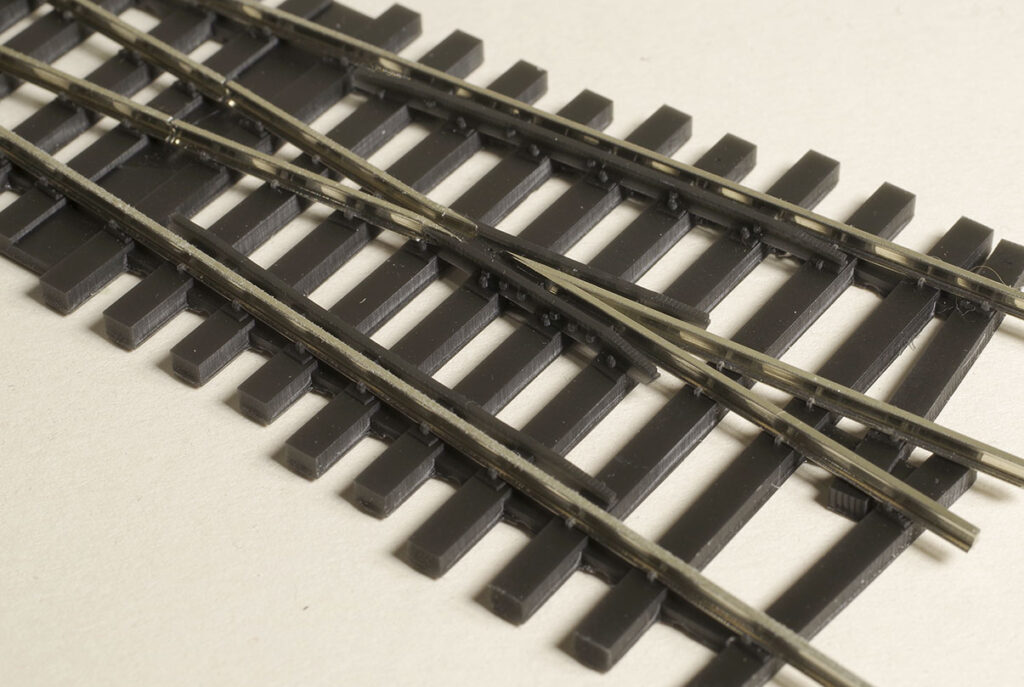
The result: The prototype turnout for the ‘Y’ at the yard entrance. Still awaiting the head rods and some fishplates, but otherwise done.
Predictably, my solution this time around was a 3D printed base with all the detail. More or less recreating the PECO turnout to an NZR pattern. But there is quite a bit more to this than meets the eye at first glance.
As you would expect I’ve gone to some trouble to model the various rail fixings found on the real thing. Spikes, common bedplates and various special bedplates, braces and spacers feature. The turnouts are not simply dead scale representations as our narrower than scale gauge and generous flangeways alter the geometry a bit. So sleeper positioning has been moved around a bit to hopefully retain the right look without slavish adherence to the drawing. In any case I don’t have a drawing for the ‘Y’ so it is an interpretation based the drawings that I do have. The 1: 7 1/2 is based on the appropriate drawing.
Obviously a scale 3D printed track spike is not going to be especially robust. Actually, in aggregate, the printed fixings are surprisingly strong, but one of the significant features of these turnouts is that the rails are soldered to hollow brass PCB rivets inserted from below. It took a bit of fiddling to get a good method to achieve this, but once refined it is really quick. This fixing is strong but completely invisible, so very satisfactory.
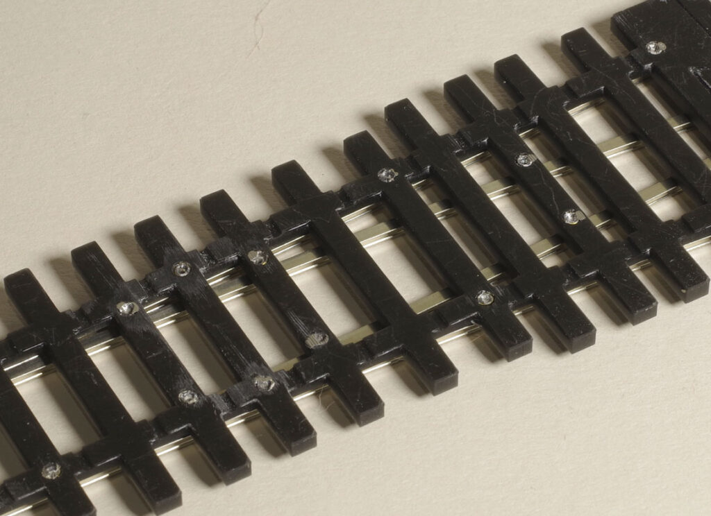
Belt and braces. Despite the fine appearance on top, these puppies are tough!
Anyone who has assembled turnouts from scratch will know that filing the rail to the correct shape is tricky, yet essential to a good result. Fergus Gillon mentioned to me that he used Fast Track jigs for 1:48 track. I took a look at their offering which, while very nice, was also very expensive for the small number of turnouts that I need. The idea of precision filing jigs is a good one though and it occurred to me that I could print such things. Obviously they would not be very durable, but they could be phenomenally accurate and easily reproduced as required. So for all the shaped pieces there is a jig derived from the CAD model to get the part just right. Typically I just file up on the jig and the part is perfect first time. Sometimes a slight tweak is needed, but either way it is very fast and accurate, even for relatively tricky bits like the frog throat (which in my turnouts is a rail/plastic interface).
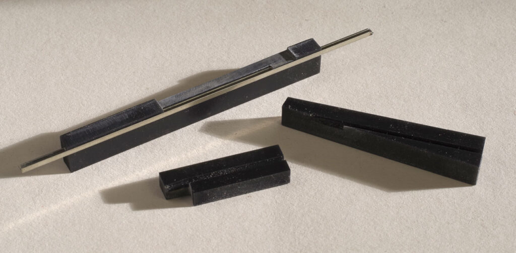
A selection of filing jigs. Slots to hold the rail are shaped to the rail profile for secure holding. In use I clamp in the vice to file.
At first glance the frog may look excessively complicated. The reasons for this are three-fold. Firstly, my assembly involves sliding the rails into the printed fixings. That precludes any sharp bends such as a one piece wing rail. Secondly, there is quite a lot of bolt detail in the frog that is nice to have and thirdly, the wings should have weathered tops so making them from plastic will certainly avoid any polish. So it is a bit complex, but the quality of the filing and shaping jigs overcame the expected difficulty.
A similar rationale applies to the guard rails, which are slightly lower than the running rails to avoid the track cleaner. One thing still to do is something similar on the frog wings.
The frog in close up. Note how the wing rails are bent and then filed back. All the running faces are in metal.
I plan on using Code 82 steel rail for the turnouts and track (although the prototypes here are nickel silver). It’s a bit over scale for 70lb (2.08mm rather than 1.93mm scale). Code 75 would be better but not available in steel. There are still a few things to sort. I may do some wood grain to the sleeper tops, the head rods need sorting and the models need the odd tweak. I’ve done the 1:7 1/2 turnout as well and, of course, left and right are just mirror images which is really easy in either CAD or print software.
So I’m really happy. The turnouts are operationally nice and cosmetically they will fit in well with everything else on the layout. A turnout takes 30 minutes to print and a pleasant hour or two to build to the level illustrated here. The project took a week on and off to develop, so overall a very satisfying exercise and tangible progress.