
At least they should.
Having recently enjoyed the relatively novel experience of finishing (as opposed to nearly finshing) a locomotive, I find that I rather enjoyed it. It did give me pause to consider why I don’t do it more often and to wonder what needs to be done to finish the small stud of steamers currently consigned to shops (or in some cases still languishing in increasingly tatty kit boxes).
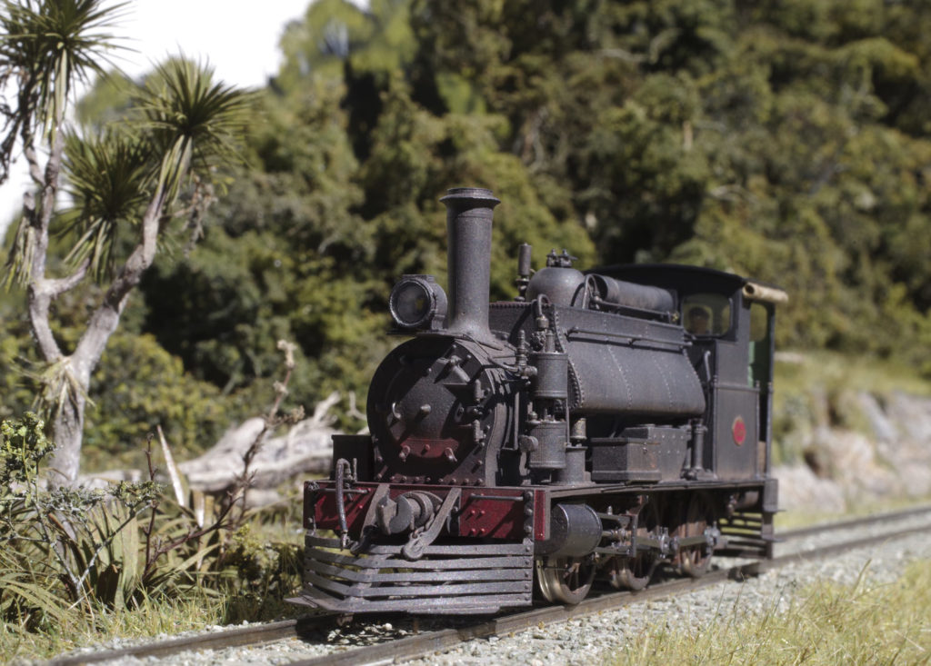
Something of a novelty: A finished model for personal pleasure.
Like so much in life the hurdles are largely mental. If it were possible for all locomotive builds to move smoothly from conception to completion with nothing but routine challenges, where the end result was more or less assured at the outset then I’m sure I would have finished more. What prevents this occurring is that I have inevitably striven for a level of engineering, detail and finish typically slightly beyond my grasp. As such, models get parked under categories such as “Don’t have the parts”, “Don’t have the tools”, “Don’t have the skill”, “Have no idea how to do this” and the more frustrating “Needs rework”. I use the term ‘parked’ advisedly as the models are not abandoned and, for the most part, have been tidily put away against the day when whatever impediment presented itself has been overcome. Of course, someone with a different mindset might go around or through the hurdle and settle for a somewhat compromised result – but a result nonetheless. That is not my way.
So what’s changed?
“Don’t have the parts” is very seldom a factor these days. If I cannot make it the Internet can almost inevitably provide it.
“Don’t have the tools” is also less of a problem as a) I have collected quite a few, b) the Internet.
“Don’t have the skill” applies less as I realise if I don’t have it now I probably never will so I need to get over myself, but also I’ve started to try to structure model building so less ‘skill’ is required.
“No idea” has been largely fixed by experience and a slowly evolving somewhat standard procedure, more of which below.
“Needs rework” is still a mental block. Eased somewhat if the road to completion is clear.
For at least 30 years it has been possible to build many, if not most, NZR steam locomotives in 1:64 from kits. However, such locomotives have generally not held much attraction to me because:
- They are often not very accurately to scale due to the manufacturing processes, skill of the patternmaker, and/or various limitations of materials available. It is not so much that I’m a rivet counter, but even someone unfamiliar with the prototype can readily tell there are deficiencies. This is not a criticism, as most of these kits are a product of their time and were ground-breaking when originally produced, but most don’t hold up all that well against a modern kit or ready-to-run (not that the latter is an option for NZR modellers).
- They often run poorly, and much of the cause is not due to the builder. In short, a rigid chassis, on injection moulded wheels, with mechanicals of mediocre accuracy with an average drive arrangement and wire pickups has too much that can go wrong to be a reliable solution. The gifted can doubtless build them, but there are better ways.
At about the time I might have started buying up such kits, I started reading Model Railway Journal and saw that better things were possible. One could, and some have, taken the standards exhibited in MRJ and reworked the available NZR offerings into lovely models, but that is not an approach that has appealed to me. My course was to scratchbuild or to manufacture my own kits to enable me to take advantage of manufacturing techniques such as casting, etching and latterly 3D printing and laser cutting.
I never set out to develop a standard method, and I still don’t entirely have one, but on reflection a de facto standard is apparent in the way I’ve tackled most of the builds. I thought I’d lay this out here, in the hope it might help others. Not that this is the only approach or, neccessarily, the best approach, but experience shows that it works for me. It’s certainly not original either. I’ve simply adapted the work of others into a procedure that suits me. I’ve also obtained, designed and/or manufactured parts and tools that make my chosen method much easier. Quite a few of these bits are available in the Emporium. What I have always striven for is a method/approach that minimises the need for skill, is sound in principle (meaning it should run well and for a long time), and looks like the real thing. These drivers are not entirely aligned and at times there are trade offs to be made, but they are the ideal.
The first thing I’ve started to do at the planning stage is to consider what constitutes the ‘chassis’ or underframe. Classically this might be anything below the footplate, but in a prototype with cowcatchers there is a real advantage in having the extremities of the frame as part of the superstructure. This is generally quite easy to do as the frames of the real thing often had extensions at either end of the main frames proper. The joint in the frames can be hidden behind cylinders or the joining plates fitted to the prototype. By dividing the chassis into the mechanical bit (carrying the wheels) and cosmetic bits (carrying the headstocks/couplers/cowcatchers) the loco is more easily broken down and parts are more robust that they would otherwise be. Electrically, we are managing insulation in areas that are hidden and robust, not at the extemities that would otherwise be relatively weak and visible.
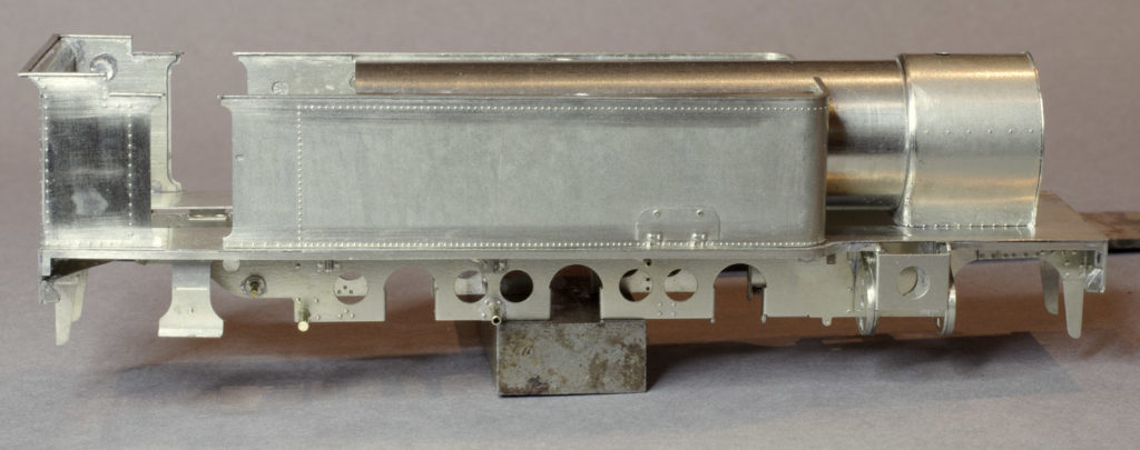
A developing W. The ‘chassis’ here is split under the doubling plate just forward of the cylinders and at the footplate bracket in line with the first row of bunker rivets. It’s hard to see – which shows it isn’t hard to hide. Note also the nice wide guides for the main bearings.
The next consideration is suspension; meaning compensation, springing or both. To date I’ve only used 3-point compensation on driving wheels. More particularly I have generally arranged this with no fixed axle. The principle of compensation is to support the locomotive in 3 points via a number of beams and pivots. This ensures that all wheels are on the track at all times with similar loading to each. This, of course, means that any inclination to derail is minimised and pick up is as good as it can be. By having no fixed axle the ride of the loco is greatly improved since, when an obstacle is encountered, the obstructed wheel moves but the travel is equalised over all of the compensated wheels. Proper springing would accomplish the same thing with even better ride (and I hope to try it), but properly engineered springing is tricky to do. Bottomed out coil springs are not the same thing at all.
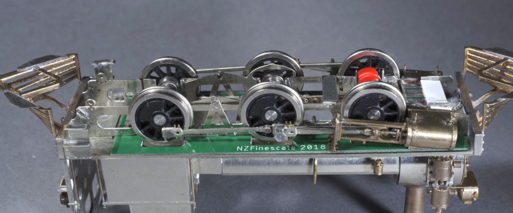
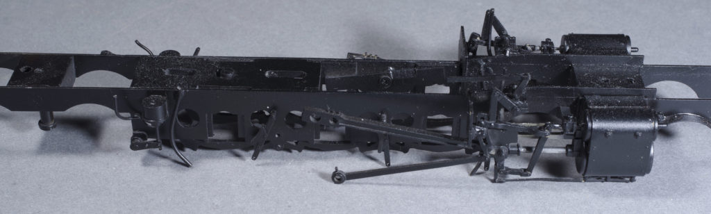
A long frame F. The chassis is split just inside the rear drivers and half way through the cylinders. The prototype compensation pivots on the rear two pairs of drivers are used and the beam parts also carry a representation of the springs. The transverse beam is the orange part clipped to the bearings of the leading drivers.
If wheels are going to have vertical movement then the axle must run in a bearing that needs to be retained in some sort of guide. In most recent locomotive builds the frames have been etched and the vertical guides provided. However I have also etched separate guides that can be fitted to plain frames. The bearings need to be supported on beams to achieve the compensation. On 6-coupled locomotives this means two longitudinal beams across two axles and a transverse beam across the third, all pivoted in the middle. On the W and the F the prototype used similar beams which means that they could be modelled working. For the transverse beam (which needs to be insulating) I developed a 3D printed unit that clips onto the main bearings – sorted in a few seconds.
The ready availability of small, cost-effective bearing races from China prompted me to use these as a standard. A 3mm bore bearing has an OD of 6mm, which is readily accommodated in a scale chassis and they are wide enough to provide plenty of room to take the compensation beams. Ball races are very low resistance, and there is no wear on the axle as there tends to be with brass/bronze plain bearings. They also tend to be sealed and lubed for life which is useful. If there is a question of longevity, they cannot be worse than plain bearings that fail quite quickly in service.
Your typical model locomotive is a fairly simple mechanism, but there are a few things that need to be got right if they are to run smoothly and well without any untoward motion (waddling). The wheels must be concentric and true to the axles. The rod centres MUST match the wheel centres. Crank throws must be equal on all wheels and the crankpins must be true. Quartering must be precise. This can be much easier said than done. While there is some room for error/tolerance, the more things are out the more compromise is required and the more appearance and running will suffer. Taking time to make up jigs for precise wheel fitting and quartering is well spent. My preferred system is turned metal wheels, tires turned on the axle and crankpins turned on the wheel. This is a deluxe solution not for everyone, but it does mean that I know that all those alignment issues will be close enough to perfect to ensure good running. If scratchbuilding or reworking a chassis, the use of jig axles to match rod and wheel centres is not difficult but essential to get this important relationship right (My etched hornguides are handy here too).
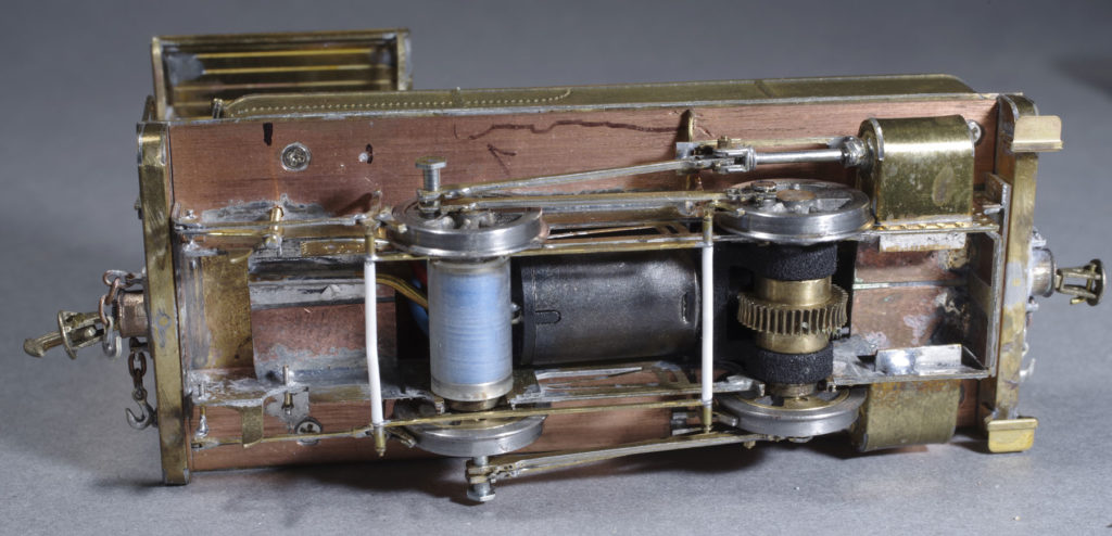
MMW Dubs A. Split frame, metal (scale) wheels, 3d printed box (using the original gearset), Acrylic tube transverse beam, 5mm OD/2mm bore ball races. North Yard crank pins which need sorting. There are refinements here not envisaged in the kit, but good flexible design meant they were very easy to add.
I am a great fan of split frames. This means that each frame is live to the wheels, and that they are insulated from one another. Axles also need to be split in this sytem. Why go to this trouble? Firstly it isn’t much trouble. I have etched PCB spacers than make assembly very easy and NY produce the split axles (or they can be made up relatively easily). On the plus side pick ups are not required if you use metal wheels (which are visually much nicer than plastic). Electrically very simple, although a bit more care needs to be applied to insulation. Personally, the use of metal wheels is a major plus. I have the capacity to make them very close to the prototype and machining means they will be more accurate than moulded wheels can be. Digital technology means that any wheel can be produced relatively cost-effectively. I also like scale wheel profiles. Not for everyone, but a real bonus as you get an extra 0.8mm clearance per side (or thereabouts) between crankpin heads and crossheads.
Long term resident of the ‘too-hard-basket’ entirely scratchbuilt WE377. This chassis is around 30 years old, but most of the principles are here. Transverse beam pivots on the screw over the rear axle (adjusts ride height). Longitudinal beams can be seen above the leading pair. Split frame, mainly with Tufnol blocks this time. This loco is due new wheels, drive and a leading truck. I’ve resolved to change as little as possible to preserve it’s provenance. A slight diversion is that it needs 5mm OD flanged bearings, which means 2mm axles and the associated complication in the drive.
Like just about every 3/16″ modeller I used Sagami/Mashima 5-pole motors and various commercial gearboxes. The Japanese motors are no more, and I have moved to Chinese coreless motors. These are a similar price but produce around 5x the power for the same format with very low current draw (Similar Swiss motors have long been the choice in expensive locos – but you pay a lot more for them). This means that a smaller motor can be fitted, which makes design easier without compromising the outline or detail of the model. Gearboxes are still available, but those most frequently used by NZR modellers use moulded gears, are inflexible as to layout, and can wear relatively quickly due to the use of plain bearings. It dawned on me one day, while chasing down a tight spot in a mechanism, that the usual boxes only have a reduction at the worm. This means that the gears in the box rotate with the same frequency as the wheels and any tightness in the box will look like tightness in the model. Moulded gears are not super accurate, and some gearboxes I’ve encountered definitely had tight spots – which is frustrating to find. Even more frustrating if you have a poor runner and have yet to work out the gearbox is the problem. My solution to this was to source machined gears and to assemble these in a 3D printed box using ball race bearings. These gearboxes mount onto the main bearings of the driven axle meaning that mesh and alignment should be maintained. The result is very smooth and quiet.
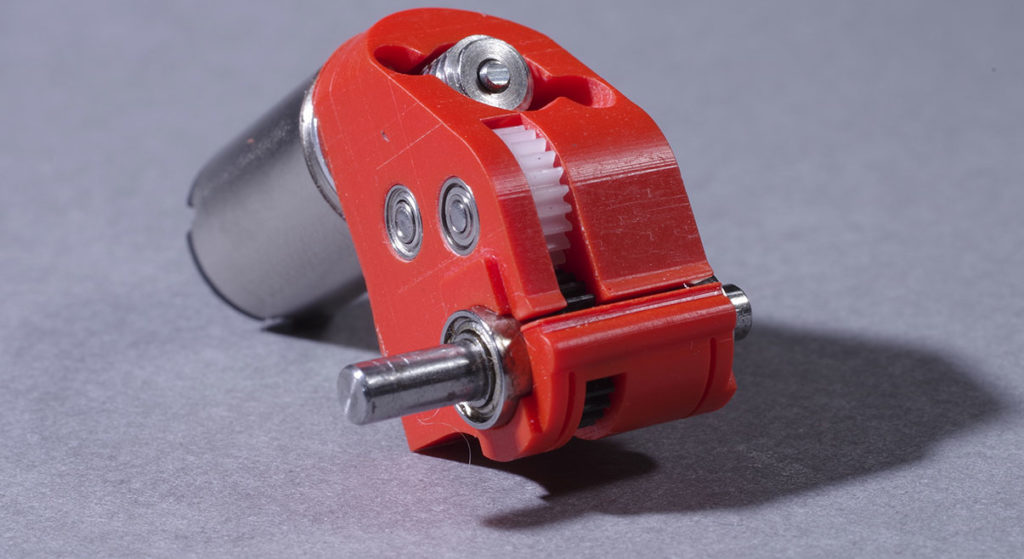
50:1 2-stage gearbox and 1219 coreless motor for the F.
The final consideration is the motion. I haven’t done anything particularly clever here except to use original drawings to produce truly scale castings, and to use steel or stainless dowels for piston rods. Sometimes the odd liberty has been taken to manage clearance and tolerance in the model, but this can all be tested in the digital model before committing to castings. When assembled neatly they look and work as you would expect them to. Fiddly, for sure, but not that difficult as all the parts are clean, sharp and fit as they should. There are very simple techniques to allow safe and reliable soldering of close fitting parts.
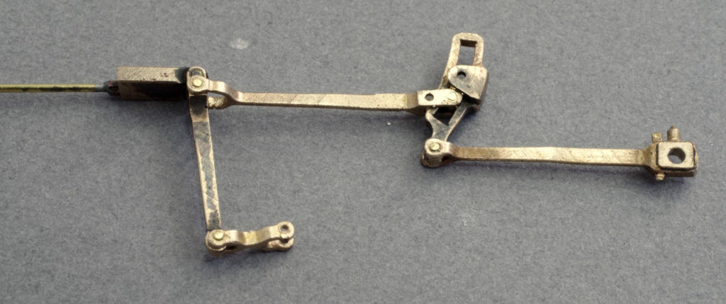
W motion during assembly. Photo from the kit instructions.
I appreciate that this methodology is not available to all. Even those with the machine tools to mange cast wheels will likely not have the equipment to produce those castings. Custom drives, and valve gear are not for everyone. However it is not out of reach either…
- Design incorporating compensation can be done the traditional way or using CAD (assuming you are not building a kit where it has been done for you).
- Jig axle techniques have been described elsewhere and are accessible, particularly when combined with etched hornguides.
- There are designs and jigs around to achieve wheel fitting and quartering.
- Split frame essentials are available.
- Cast wheels are increasingly available (ask as not all are listed. Some are owned by others but may still be available)
- NZF supply motors, and can supply bearings and gearboxes on request.
- We can design motion parts or produce parts from your digital models – or propose a project on the Wishlist.
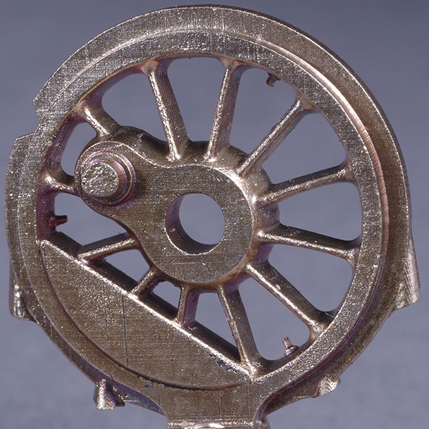
X class driver in 1/64.
The revelation in the recently completed builds is how nicely it all works. It’s not exactly a surprise, as all the design decisions have been made to counter established issues and problems, but I’ve always approached final assembly and getting things running with some trepidation. It hasn’t all been plain sailing, but for the most part this hurdle has, for the most part, been a mental one.